The ChipProg-ISP is an inexpensive universal device programmer for programming devices installed in the equipment. This type of programming is known as “in-system” or “in-circuit” programming. The ChipProg-ISP supports serial EPROM and EEPROM flash memory devices and embedded microcontrollers with the code and data memory programmable via different types of serial ports: UART, JTAG, SWD, SPI and other types, including proprietary interfaces.
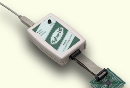
The programmer has three LEDs for displaying the programming status (“Good”, “Busy”, “Error”) and the “Start” button for fast launch of the pre-programmed command chains. The tool shown on the picture is very small and requires no power adapter for the operations - it gets power from the USB computer port.
.
Connecting ChipProg-ISP to the target
The programmer has a 14-pin output connector BH-14R. A variety of Phyton adapting cables allow connecting to the target. A simple pin-to-pin ribbon cable AS-ISP-CABLE is supplied with the programmer by default, and other cables (adapters) can be ordered on demand. The BH-14R connector output information signals for the chip programming and some service signals that enable using the programmer in the automated programming and testing equipment. See the BH-14R pinout:
ChipProg-ISP BH-14R connector |
Logical signal |
1 |
Target specific* |
2 |
Target specific* |
3 |
Target specific* |
4 |
Target specific* |
5 |
Target specific* |
6 |
Target specific* |
7 |
Target specific* |
8 |
Target specific* |
9 |
GND |
10 |
Target specific* |
11 |
/Start |
12 |
/Error |
13 |
/Good |
14 |
/Busy |
Signals on the pins #1 to #9 and on the pin #10 are used for transmitting and receiving information and synchro impulses to and from the target device. These signals are target specific and depend on the type of target device or a family in general (AVR, PIC, etc.) - see here. They also are shown in the adapters wiring diagrams; see the file adapters.chm included in the ChipProgUSB set.
The pin #9 must be connected to the target's ground.
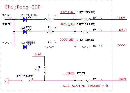
The signals on the output pins #12, #13 and #14 represent the programmer statuses - logical '0' means an active status, logical '1' - passive. E.g.:
/Error – the operation has failed;
/Good – the operation completed successfully;
/Busy – the programmer is in a process of executing some operation.
An active signal on the input pin #11 (log.'0') starts the preset operation, the device programming by default. Activation of this signal, e.g. a falling edge, is equivalent to pushing the "Start" button on the programmer. See the diagram below:
Read also In-System Programming for different devices.
•One programmer unit
•One universal ribbon cable wired pin-to-pin
•One USB link cable
•One CD with the ChipProgUSB software
Optionally the package may include one or more programming cable-adapters (if ordered with the programmer) and a “QuickStart” printed manual. See also for more details: