DIP28/BH16 specialized adapter for in system programming of NEC microcontrollers.
Connections to the target devices:
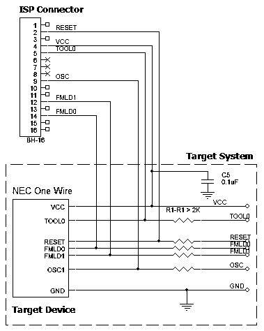
AE-ISP-NEC connection for the NEC microconrollers for one-wire UART
Recommended connection:
Powering the target device:
There are two alternative options for powering the targets:
1. The target gets power from the programmer (Vdd). This is possible only if the target does not consume too much energy. A capacity of the target power circuitry should not exceed 50 uF.
2. The target gets power from a built-in or external power supply. In this case the power output from the programmer should not be connected with the target. The target system should be tolerant to applying logical signals with the voltage levels exceeding the voltages on the target.
NOTE! It is strictly prohibited to power the target from both the programmer and built-in or external power supply simultaneously.
Isolating resistors:
Purpose of the R1..R6 resistors is to isolate the programmed chip from rest of target system. Recommended value of resistors R1..R6 is 2k or more. You can also use jumpers instead of the resistors.
ISP characteristics:
1. Programmer''s output capability:
1.1 Vcc - 80 mA;
1.2 Vpp - 50 mA;
1.3 logical pins - 5 mA.
2. The cable length should be less then one foot.
Adapter Connection Table:
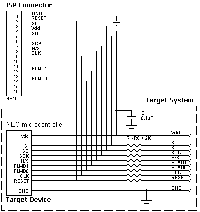
AE-ISP-NEC connection for the NEC microconrollers in SPI mode
Recommended connection:
Powering the target device:
There are two alternative options for powering the targets:
1. The target gets power from the programmer (Vdd). This is possible only if the target does not consume too much energy. A capacity of the target power circuitry should not exceed 50 uF.
2. The target gets power from a built-in or external power supply. In this case the power output from the programmer should not be connected with the target. The target system should be tolerant to applying logical signals with the voltage levels exceeding the voltages on the target.
NOTE! It is strictly prohibited to power the target from both the programmer and built-in or external power supply simultaneously.
Isolating resistors:
Purpose of the R1..R8 resistors is to isolate the programmed chip from rest of target system. Recommended value of resistors R1..R8 is 2k or more. You can also use jumpers instead of the resistors.
ISP characteristics:
1. Programmer''s output capability:
1.1 Vcc - 80 mA;
1.2 Vpp - 50 mA;
1.3 logical pins - 5 mA.
2. The cable length should be less then one foot.
Adapter Connection Table:
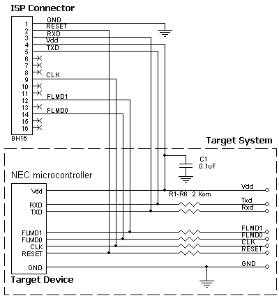
AE-ISP-NEC connection for the NEC microconrollers in UART mode
Recommended connection:
Powering the target device:
There are two alternative options for powering the targets:
1. The target gets power from the programmer (Vdd). This is possible only if the target does not consume too much energy. A capacity of the target power circuitry should not exceed 50 uF.
2. The target gets power from a built-in or external power supply. In this case the power output from the programmer should not be connected with the target. The target system should be tolerant to applying logical signals with the voltage levels exceeding the voltages on the target.
NOTE! It is strictly prohibited to power the target from both the programmer and built-in or external power supply simultaneously.
Isolating resistors:
Purpose of the R1..R5 resistors is to isolate the programmed chip from rest of target system. Recommended value of resistors R1..R5 is 2k or more. You can also use jumpers instead of the resistors.
ISP characteristics:
1. Programmer''s output capability:
1.1 Vcc - 80 mA;
1.2 Vpp - 50 mA;
1.3 logical pins - 5 mA.
2. The cable length should be less then one foot.
Adapter Connection Table:
Adapter connection table: