Device: EFM8BB31F16I-D-QSOP24 [ISP Mode]
- Manufacturer(s): Silicon Labs
- Device type: Microcontroller / 8051
Silicon Labs EFM8BB31F16I-D-QSOP24 [ISP Mode] is programmed "in-system", i.e. being installed on a board. The matrix below lists Phyton device programmers that support the EFM8BB31F16I-D-QSOP24 [ISP Mode] device in-system programming and appropriate cable-Adapters or device library licenses.
| EFM8BB31F16I-D-QSOP24 [ISP Mode] is programmed by | ||
|---|---|---|
| Connection or Adapter | Device programmers | Required license |
| Connection diagrams | CPI2-B1-SL51 | CPI2-D-SL51 device library license is preloaded |
| Connection diagrams | CPI2-B1, CPI2-Gx | CPI2-D-SL51 device library license is required |
| Connection diagrams | CPI2-B1-x (preloaded) | CPI2-D-SL51 device library license is required |
| AE-ISP-U1 | ChipProg-481, ChipProg-48 | - |
Recommended CPI2-B1&CPI2-Gx connection (Connection for the Silicon Labs microcontrollers)
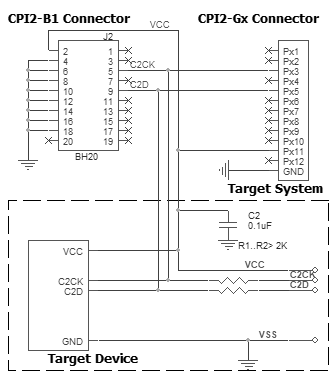
Powering the target device:
There are two alternative options for powering the targets:
1. The target gets power from the programmer (Vdd). This is possible only if the target does not consume too much energy. A capacity of the target power circuitry should not exceed 50 uF.
2. The target gets power from a built-in or external power supply. In this case the power output from the programmer should not be connected with the target. The target system should be tolerant to applying logical signals with the voltage levels exceeding the voltages on the target.
NOTE! It is strictly prohibited to power the target from both the programmer and built-in or external power supply simultaneously.
Isolating resistors:
Purpose of the resistors is to isolate the programmed chip from rest of target system. Recommended value of resistors is 2k or more. You can also use jumpers instead of the resistors.
ISP characteristics:
1. Programmer''s output capability:
1.1 Vcc - 80 mA with powering from USB and 350mA from external device programmer power supply;
1.2 Vpp - 50 mA;
1.3 logical pins - 5 mA.
2. The cable length should be less then one foot.
/Start is the input signal, active state is 0. This signal works as the Start button on the programmer.
/Error, /Good, /Busy are output logical signals, active state is 0. They indicate the programmer status and work as the corresponding LEDs on the programmer case.
Adapter Connection Table:
| CPI2-B1 TARGET connector | CPI2-Gx TARGET connector | Target Device Silabs C8051xxx |
|---|---|---|
| 1 | Px1 | - |
| 2 | Px11 | VCC |
| 3 | Px2 | - |
| 4 | GND | GND |
| 5 | Px3 | C2CK* |
| 6 | GND | GND |
| 7 | Px4 | - |
| 8 | GND | GND |
| 9 | Px5 | C2D |
| 10 | GND | GND |
| 11 | Px6 | - |
| 12 | GND | GND |
| 13 | Px7 | - |
| 14 | GND | GND |
| 15 | Px8 | - |
| 16 | GND | GND |
| 17 | Px9 | - |
| 18 | GND | GND |
| 19 | Px10 | - |
| 20 | Px12 | - |
Go Back