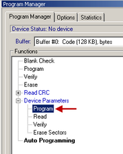
The Device and Algorithm Parameters Editor window is intended for displaying and editing (where possible) the device’s internal parameters and settings, which after editing should be programmed into a target device by executing the Program command in the Program Manager window.
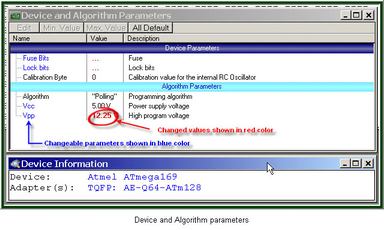
The parameters displayed into this window are split in two groups: Device Parameters and Algorithm Parameters. The groups are separated by a light blue stripe
Device Parameters |
This group includes parameters that are specific for each selected device, such as: sectors for flash memory devices, lock and fuse bits, configuration bits, boot blocks, start addresses and other controls for microcontrollers. Usually these parameters represent certain bits in a microcontroller’s Special Function Registers (SFRs). Some of these SFRs can be set in the ChipProg buffers in accordance with device manufacturers’ data sheets. But setting the parameters in the Device and Algorithms Parameters window is much easier and more intuitive. It is impossible to specify absolutely all features that may appear in future devices, and, therefore, new parameters for these new devices.
|
||
Algorithm Parameters |
This group includes parameters of the programming algorithm for the selected device – including the algorithm type and editable programming voltages. .
|
The window is separated into three columns: 1) the parameter's name, 2) its value or setting, 3) a short description. Names of the editable parameters are shown in blue; other names are shown in black. Default values in the column Value are shown in black; after changing a parameter the new value will be shown in red. If the value is too long to display the window represents it as three dot signs (‘…’). If these dots are red it means that the parameter has been edited.
In order to edit a parameter, double click its name. Some editable parameters are represented by a set of check boxes, some require to be typed in prompt boxes.
The local Device and Algorithm Parameters Editor window's toolbar includes a few buttons positioned on the top of the window:
Toolbar button |
Description
|
Edit |
Clicking on this button opens the editing dialog to modify the highlighted parameter in the format, most convenient for this parameter. A double click on the highlighted parameter also opens the editing dialog. |
Min.Value |
If the parameter to be modified has an allowed range in which it may be set, then clicking on the Min.Value button sets the minimal allowed value to the highlighted parameter. |
Max.Value |
If the parameter to be modified has an allowed range in which it may be set, then click on the Max.Value button to set the maximal allowed value to the highlighted parameter. |
Default |
Click on this button returns the default value to the highlighted parameter. |
All Default |
Click on this button returns the default values to all the parameters displayed in the window. |
Depending of the parameter's type ChipProgUSB offers the most convenient format for the parameter editing:
Method of editing |
Description
|
Drop-down menu |
When the parameter value may be picked from a few preset values the dialog offers a drop-down list with these values. Highlight a new value in the list and click OK to complete the editing. For example, some microcontrollers can be programmed to work with different types of the clock generators, so the menu prompts to select one of them.
|
Check Box dialog |
When some options can be set or reset the dialog appears in a form of several boxes indicating the default or lately set option statuses. To toggle the option check or uncheck the box. For example, some microcontrollers allow the locking of a particular part of the memory by setting several lock bits, so the menu prompts to check the lock bits represented as a set of check boxes. |
Customizing the parameter |
When the parameter value may be set freely in an allowed range the dialog offers a box for entering a new value and a history list displaying a few recently set values. The dialog prompts with the min and max values that can be set for each parameter and restricts to enter the value out of the allowed range. This type of editing is in use for setting custom values for Vcc and Vpp voltages. |