This is the simplest way to integrate LabVIEW with ChipProgUSB. In general the scenario includes: a) setting the programming session options within the ChipProg user interface and b) further operating with the programmer from the LabVIEW user interface. Here is an example of use:
1) Create a special folder for driving the ChipProgUSB software from the LabVIEW user interface - for example C:\LabView\1.
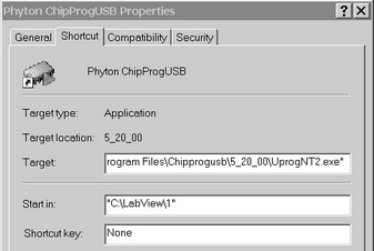
2) On the computer desktop, make a copy of the ChipProgUSB icon. Rename it for use exclusively for the LabVIEW control. Normally the path to this icon is "C:\Program Files\ChipProgUSB\x_xx_xx\UprogNT2.exe", where the 'x_xx_xx' means a current version of the ChipProgUSB software. Right click on the created icon, select Properties, tab Shortcut and in the field Start in change the path to the C:\LabView\1 (see below):
3) Power the ChipProg device programmer, connect it to a USB port of your PC and launch the ChipProgUSB program by clicking the icon in the folder C:\LabView\1. When the programmer's user interface opens, begin setting the programming session options by choosing the target device (for example by pressing the F3 hot key). Then, after choosing the device, it is necessary to set up the programming options and parameters within the ChipProgUSB windows, menus and dialogs below if these options differ from the default ones. The following options are settable within the ChipProgUSB GUI:
- Settings in the Program Manager window ,such as selecting functions to be included into the Auto Programming batch (button Edit Auto...); these include Split data, Insert test, Auto Detect and other settings in the Options tab; the number of chips to be programmed during the programming session and other options in the Statistics tab.
- Settings in the Device and Algorithm Parameters Editor window that are device-specific, such as boot vectors, fuses, lock bits, Vcc voltage, oscillator frequencies, etc.
- Settings in the sub dialogs accessible through the Serialization, Checksum, Log file... menu, such as setting algorithms for writing serial numbers and custom signatures into the devices being programmed, a buffer checksum calculation, programming custom shadow areas, dumping data to log files, etc.
- Miscellaneous settings in the sub dialogs accessible through the Preferences and Environment menus, such as color, fonts, sounds, etc.
Then complete the programming session by means of including an appropriate command line keys into the command line pattern:
- Specifying a method of control through the programming session (key /S);
- Choosing the target device being programmed (key /C<manufacturer>^<device>);
- Loading the file to be programmed and the file format (key /L<file name> /F<file format>);
- Specifying the Auto Programming mode (key /A);
- Launching the programmer into the hidden mode, when the ChipProgUSB GUI invisible (key /I2).
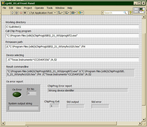
4) To launch a ChipProg in the command line mode use a standard LabVIEW module SystemExec. The picture below show a screen shot of the LabVIEW GUI front panel with the cp48_01.vi module loaded:
Notes:
- The device specified in the command line by the key /C must be the same as chosen in the ChipProgUSB user interface.
- Including the /I2 key in the command line makes the ChipProgUSB application main window invisible, suppresses display of error messages but copies them to the Windows clipboard. If the session completes successfully the ChipProgUSB application returns the error code 0; in case of errors, 1 is returned.
If, for example, you want to program a HEX file myfw1020.hex located in the folder Program Files (x86)\ChipProgUSB\5_21_00 into the flash memory of a lot of Texas Instruments CC2540F256 devices, then the command line should have the following format:
"C:\Program Files (x86)\ChipProgUSB\5_21_00\UprogNT2.exe" /L"Program Files (x86)\ChipProgUSB\5_21_00\myfw1020.hex" /FH /C"Texas Instruments^CC2540F256" /A /I2
4) To launch a ChipProg in the command line mode use the standard LabVIEW SystemExec module. The picture below shows a screen shot of the LabVIEW GUI front panel with the cp48_01.vi module loaded:
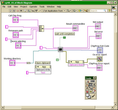
and below is the same module block diagram:
The <ChipProg launches in the hidden mode; its GUI remains invisible during the programming session. If no errors occur the ChipProg Exit box returns the code 0, otherwise 1 is returned. The error is displayed in the ChipProg Error box report.