First, make the following preparations for making a project that will control the programming session with the SUI. Start from the following steps:
•Menu Configuration - select the target device;
•Menu Configuration - set up the buffer;
•Menu Configuration - set up options for the device serialization, writing check sum and signatures, and log file controls;
•Windows Device and Algorithm Parameters Editor - specify the options different from default for a chosen device.
•Windows Program Manager > tab Program Manager > the Edit Auto dialog - configure the Auto Programming batch of functions;
•Windows Program Manager > tab Options - set the programming options;
•Windows Program Manager > tab Statistics - set a number of chips to be programmed and other options
Working in the SUI mode disables counting down the programmed chips (this option can be set in the tab Statistics), an operator can watch only numbers of successfully programmed and failed chips. Other options set in this tab remain in force.
Second, create the project. Select the menu Project > New. In the Project Options dialog specify the project name, file name and format and other options; then click the OK button to store the project. It is absolutely crucial to store the project. Then follow to setting the SUI options.
Under the Configuration menu click the command Simplified mode editor. This will open the Simplified Mode Setup window with the SUI window docked to the first window at left (see below). Any changes made in the Simplified Mode Setup window immediately become visible in the SUI window. Clicking the OK button in the Simplified Mode Setup window completes the SUI setup, the window closes and the button Return to editing appears in the SUI window. This allows quick switching back and forth from SUI session editing to programming chips.
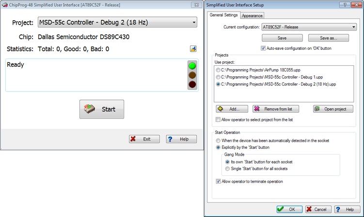
The General Settings Tab
The Current configuration field displays the name of the currently chosen SUI configuration. The configuration files with the extension .smc are located in the folder SMConfig; this folder is located in the working ChipProgUSB folder. The Save button allows saving the configuration under the name entered in the field Current configuration; the Save as... button allows saving it under another name. If the Auto-save configuration on 'OK' button box is checked then clicking the OK button at the bottom of this tab will automatically save the current configuration and close the dialog.
The Projects pane lists all the projects associated with the current configuration. When you open the Simplified Mode Setup window for the first time, the Projects list is blank. To add a project use the + Add button. One configuration may include more than one project if it is necessary to enable an operator to change projects without restarting the programmer. If Allow operator to select project from the list box is checked, then the SUI window displays all the projects associated with the current configuration; otherwise, it displays only one project selected from the Use project list. To remove a project from the Use project list, highlight it and click the x Remove from list button. This will remove the project from the list but not from the disc. The Open project button loads a selected project and does not close the editor.
The Start Programming pane gathers appropriate settings. By checking the When the device has been automatically detected in the socket radio button you allow immediate launching of the programming operation upon detecting the chip in the ChipProg socket. If this option is checked, the Start button (or buttons in the gang mode) in the SUI window will be replaced with the auto detect acknowledgment indicator.
Alternatively, the programming operation can be initiated by operator manipulation. Check the Explicitly by the 'Start' button radio button and, if you use the gang programming mode, check one of two radio buttons: Its own 'Start' button for each socket or Single 'Start' button for all sockets. Checking the Its own Start button for each socket option radio button allows an operator to replace a chip in a socket and immediately press the 'Start' button so the chips are programmed asynchronously. Checking the Single 'Start' button for all sockets option radio button allows an operator to insert as many chips as desired in programming sockets at once (for example, 4 chips when using the ChipProg-G41 gang programmer) and then to press any 'Start' button to initiate concurrent chip programming on all programming sites. In this mode, replacing the target chips is possible only upon completing the programming procedures on all sites.
The only Auto Programming command batch can be initiated by pressing the Start button. This command can be executed either by pressing the mechanical button on the ChipProg unit or by clicking the 'Start' virtual button in the SUI window.
If the box Allow programming termination by operator is checked, an operator is able to stop the programming by clicking the Exit button in the SUI window, otherwise the operator can only initiate device programming.
The Appearance Tab
Here you can individually choose the type, size and color of the Default Font for each element that can be displayed in the SUI window: Project name, Device part number, Statistics, Device operation status, and "Start" button. Move up and Move down allow customization of the element position in the SUI window. By checking appropriate boxes under the Display elements titles you can enable displaying them in the SUI window.
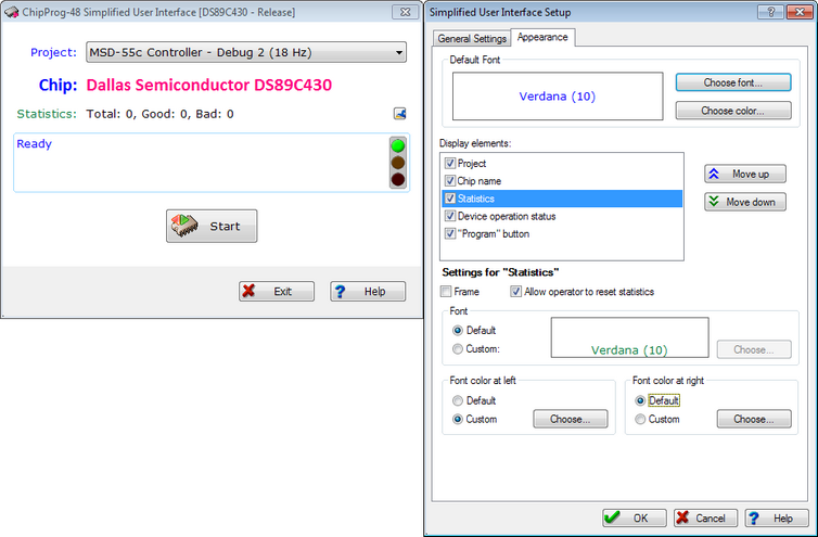
Then, by highlighting an element enabled for display in the SUI window, you can individually set an appearance of each element if you wish its appearance to differ from the default and from other elements. Checking the Frame box causes a thin blue frame to appear around the element's field. Radio buttons Font, Font color at left and Font color at right enable the creation of appearances that distinguish the elements displayed in the SUI windows.
When the Statistics element is highlighted, the box Allow operator to reset statistics appears. Checking this box enables an operator to clear the current programming statistics.
When the Device operation status element is highlighted, two extra boxes: Serial number and Checksum appear. Checking these boxes enables the serial number and the check sum written into the last programmed device to be displayed below the status line.