Standard ISP cable for CPI2-B1 programmer.
Connections to the target devices:
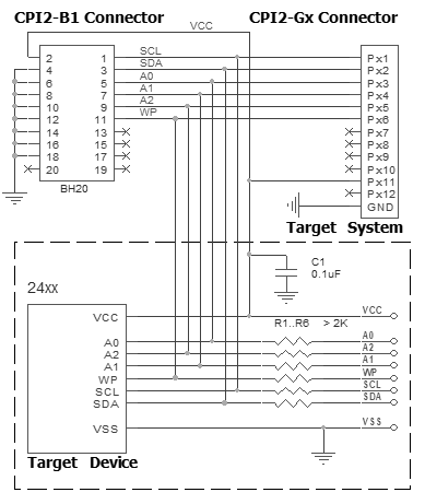
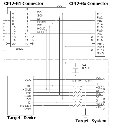
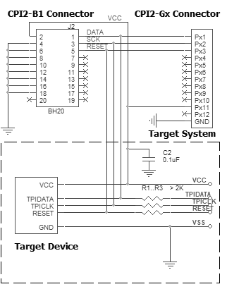
Connection for the 24xx devices
Recommended connection:
Powering the target device:
There are two alternative options for powering the targets:
1. The target gets power from the programmer (Vdd). This is possible only if the target does not consume too much energy. A capacity of the target power circuitry should not exceed 50 uF.
2. The target gets power from a built-in or external power supply. In this case the power output from the programmer should not be connected with the target. The target system should be tolerant to applying logical signals with the voltage levels exceeding the voltages on the target.
NOTE! It is strictly prohibited to power the target from both the programmer and built-in or external power supply simultaneously.
Isolating resistors:
Purpose of the resistors is to isolate the programmed chip from rest of target system. Recommended value of resistors is 2k or more. You can also use jumpers instead of the resistors.
ISP characteristics:
1. Programmer''s output capability:
1.1 Vcc - 80 mA with powering from USB and 350mA from external device programmer power supply;
1.2 Vpp - 50 mA;
1.3 logical pins - 5 mA.
2. The cable length should be less then one foot.
/Start is the input signal, active state is 0. This signal works as the Start button on the programmer.
/Error, /Good, /Busy are output logical signals, active state is 0. They indicate the programmer status and work as the corresponding LEDs on the programmer case.
Adapter Connection Table:
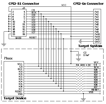
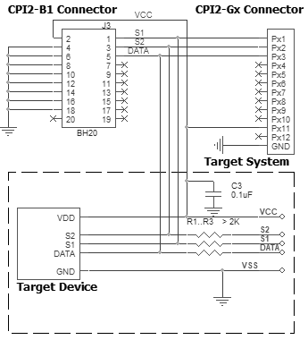
Connection for the 79xxx devices
Recommended connection:
Powering the target device:
There are two alternative options for powering the targets:
1. The target gets power from the programmer (Vdd). This is possible only if the target does not consume too much energy. A capacity of the target power circuitry should not exceed 50 uF.
2. The target gets power from a built-in or external power supply. In this case the power output from the programmer should not be connected with the target. The target system should be tolerant to applying logical signals with the voltage levels exceeding the voltages on the target.
NOTE! It is strictly prohibited to power the target from both the programmer and built-in or external power supply simultaneously.
Isolating resistors:
Purpose of the resistors is to isolate the programmed chip from rest of target system. Recommended value of resistors is 2k or more. You can also use jumpers instead of the resistors.
ISP characteristics:
1. Programmer''s output capability:
1.1 Vcc - 80 mA with powering from USB and 350mA from external device programmer power supply;
1.2 Vpp - 50 mA;
1.3 logical pins - 5 mA.
2. The cable length should be less then one foot.
/Start is the input signal, active state is 0. This signal works as the Start button on the programmer.
/Error, /Good, /Busy are output logical signals, active state is 0. They indicate the programmer status and work as the corresponding LEDs on the programmer case.
Adapter Connection Table:
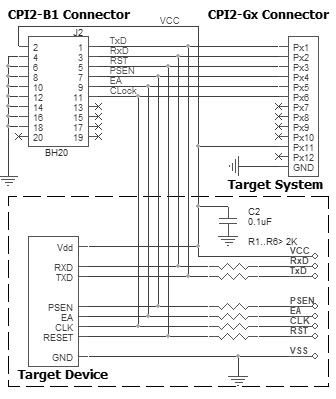
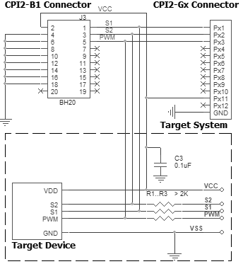
Connection for the 8051 devices via BL
Recommended connection:
Powering the target device:
There are two alternative options for powering the targets:
1. The target gets power from the programmer (Vdd). This is possible only if the target does not consume too much energy. A capacity of the target power circuitry should not exceed 50 uF.
2. The target gets power from a built-in or external power supply. In this case the power output from the programmer should not be connected with the target. The target system should be tolerant to applying logical signals with the voltage levels exceeding the voltages on the target.
NOTE! It is strictly prohibited to power the target from both the programmer and built-in or external power supply simultaneously.
Isolating resistors:
Purpose of the resistors is to isolate the programmed chip from rest of target system. Recommended value of resistors is 2k or more. You can also use jumpers instead of the resistors.
ISP characteristics:
1. Programmer''s output capability:
1.1 Vcc - 80 mA with powering from USB and 350mA from external device programmer power supply;
1.2 Vpp - 50 mA;
1.3 logical pins - 5 mA.
2. The cable length should be less then one foot.
/Start is the input signal, active state is 0. This signal works as the Start button on the programmer.
/Error, /Good, /Busy are output logical signals, active state is 0. They indicate the programmer status and work as the corresponding LEDs on the programmer case.
Adapter Connection Table:
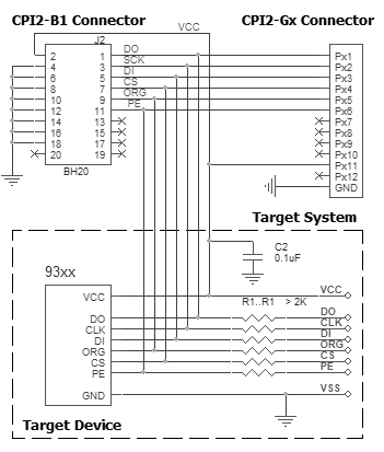
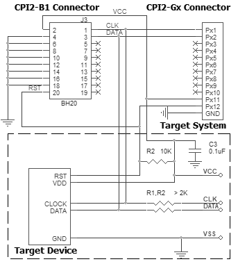
Connection for the 93xx devices
Recommended connection:
Powering the target device:
There are two alternative options for powering the targets:
1. The target gets power from the programmer (Vdd). This is possible only if the target does not consume too much energy. A capacity of the target power circuitry should not exceed 50 uF.
2. The target gets power from a built-in or external power supply. In this case the power output from the programmer should not be connected with the target. The target system should be tolerant to applying logical signals with the voltage levels exceeding the voltages on the target.
NOTE! It is strictly prohibited to power the target from both the programmer and built-in or external power supply simultaneously.
Isolating resistors:
Purpose of the resistors is to isolate the programmed chip from rest of target system. Recommended value of resistors is 2k or more. You can also use jumpers instead of the resistors.
ISP characteristics:
1. Programmer''s output capability:
1.1 Vcc - 80 mA with powering from USB and 350mA from external device programmer power supply;
1.2 Vpp - 50 mA;
1.3 logical pins - 5 mA.
2. The cable length should be less then one foot.
/Start is the input signal, active state is 0. This signal works as the Start button on the programmer.
/Error, /Good, /Busy are output logical signals, active state is 0. They indicate the programmer status and work as the corresponding LEDs on the programmer case.
Adapter Connection Table:
* Must be connected if there is no connection in a system.
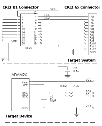
Connection for the ADAM2x
Recommended connection:
Powering the target device:
There are two alternative options for powering the targets:
1. The target gets power from the programmer (Vdd). This is possible only if the target does not consume too much energy. A capacity of the target power circuitry should not exceed 50 uF.
2. The target gets power from a built-in or external power supply. In this case the power output from the programmer should not be connected with the target. The target system should be tolerant to applying logical signals with the voltage levels exceeding the voltages on the target.
NOTE! It is strictly prohibited to power the target from both the programmer and built-in or external power supply simultaneously.
Isolating resistors:
Purpose of the resistors is to isolate the programmed chip from rest of target system. Recommended value of resistors is 2k or more. You can also use jumpers instead of the resistors.
ISP characteristics:
1. Programmer''s output capability:
1.1 Vcc - 80 mA with powering from USB and 350mA from external device programmer power supply;
1.2 Vpp - 50 mA;
1.3 logical pins - 5 mA.
2. The cable length should be less then one foot.
/Start is the input signal, active state is 0. This signal works as the Start button on the programmer.
/Error, /Good, /Busy are output logical signals, active state is 0. They indicate the programmer status and work as the corresponding LEDs on the programmer case.
Adapter Connection Table:
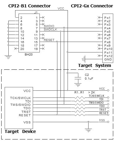
Connection for the ARM/Cortex microcontrollers via SWD
Recommended connection:
Powering the target device:
There are two alternative options for powering the targets:
1. The target gets power from the programmer (Vdd). This is possible only if the target does not consume too much energy. A capacity of the target power circuitry should not exceed 50 uF.
2. The target gets power from a built-in or external power supply. In this case the power output from the programmer should not be connected with the target. The target system should be tolerant to applying logical signals with the voltage levels exceeding the voltages on the target.
NOTE! It is strictly prohibited to power the target from both the programmer and built-in or external power supply simultaneously.
Isolating resistors:
Purpose of the resistors is to isolate the programmed chip from rest of target system. Recommended value of resistors is 2k or more. You can also use jumpers instead of the resistors.
ISP characteristics:
1. Programmer''s output capability:
1.1 Vcc - 80 mA with powering from USB and 350mA from external device programmer power supply;
1.2 Vpp - 50 mA;
1.3 logical pins - 5 mA.
2. The cable length should be less then one foot.
/Start is the input signal, active state is 0. This signal works as the Start button on the programmer.
/Error, /Good, /Busy are output logical signals, active state is 0. They indicate the programmer status and work as the corresponding LEDs on the programmer case.
Adapter Connection Table:
All power supply pins included AVdd must be powered. All ground pins included AVss must be connected together.
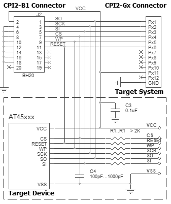
Connection for the Adesto/Atmel AT45xxx
Recommended connection:
Powering the target device:
There are two alternative options for powering the targets:
1. The target gets power from the programmer (Vdd). This is possible only if the target does not consume too much energy. A capacity of the target power circuitry should not exceed 50 uF.
2. The target gets power from a built-in or external power supply. In this case the power output from the programmer should not be connected with the target. The target system should be tolerant to applying logical signals with the voltage levels exceeding the voltages on the target.
NOTE! It is strictly prohibited to power the target from both the programmer and built-in or external power supply simultaneously.
Isolating resistors:
Purpose of the resistors is to isolate the programmed chip from rest of target system. Recommended value of resistors is 2k or more. You can also use jumpers instead of the resistors.
ISP characteristics:
1. Programmer''s output capability:
1.1 Vcc - 80 mA with powering from USB and 350mA from external device programmer power supply;
1.2 Vpp - 50 mA;
1.3 logical pins - 5 mA.
2. The cable length should be less then one foot.
/Start is the input signal, active state is 0. This signal works as the Start button on the programmer.
/Error, /Good, /Busy are output logical signals, active state is 0. They indicate the programmer status and work as the corresponding LEDs on the programmer case.
Adapter Connection Table:
Connection for the Altera EPM3xxxA/MAX2 devices
Recommended connection:
Powering the target device:
There are two alternative options for powering the targets:
1. The target gets power from the programmer (Vdd). This is possible only if the target does not consume too much energy. A capacity of the target power circuitry should not exceed 50 uF.
2. The target gets power from a built-in or external power supply. In this case the power output from the programmer should not be connected with the target. The target system should be tolerant to applying logical signals with the voltage levels exceeding the voltages on the target.
NOTE! It is strictly prohibited to power the target from both the programmer and built-in or external power supply simultaneously.
Isolating resistors:
Purpose of the resistors is to isolate the programmed chip from rest of target system. Recommended value of resistors is 2k or more. You can also use jumpers instead of the resistors.
ISP characteristics:
1. Programmer''s output capability:
1.1 Vcc - 80 mA with powering from USB and 350mA from external device programmer power supply;
1.2 Vpp - 50 mA;
1.3 logical pins - 5 mA.
2. The cable length should be less then one foot.
/Start is the input signal, active state is 0. This signal works as the Start button on the programmer.
/Error, /Good, /Busy are output logical signals, active state is 0. They indicate the programmer status and work as the corresponding LEDs on the programmer case.
Adapter Connection Table:
All power supply pins included AVdd must be powered. All ground pins included AVss must be connected together.
Connection for the Atmel AT88xx devices
Recommended connection:
Powering the target device:
There are two alternative options for powering the targets:
1. The target gets power from the programmer (Vdd). This is possible only if the target does not consume too much energy. A capacity of the target power circuitry should not exceed 50 uF.
2. The target gets power from a built-in or external power supply. In this case the power output from the programmer should not be connected with the target. The target system should be tolerant to applying logical signals with the voltage levels exceeding the voltages on the target.
NOTE! It is strictly prohibited to power the target from both the programmer and built-in or external power supply simultaneously.
Isolating resistors:
Purpose of the resistors is to isolate the programmed chip from rest of target system. Recommended value of resistors is 2k or more. You can also use jumpers instead of the resistors.
ISP characteristics:
1. Programmer''s output capability:
1.1 Vcc - 80 mA with powering from USB and 350mA from external device programmer power supply;
1.2 Vpp - 50 mA;
1.3 logical pins - 5 mA.
2. The cable length should be less then one foot.
/Start is the input signal, active state is 0. This signal works as the Start button on the programmer.
/Error, /Good, /Busy are output logical signals, active state is 0. They indicate the programmer status and work as the corresponding LEDs on the programmer case.
Adapter Connection Table:
Connection for the Cypress CY8C2xxxx devices
Recommended connection:
Powering the target device:
There are two alternative options for powering the targets:
1. The target gets power from the programmer (Vdd). This is possible only if the target does not consume too much energy. A capacity of the target power circuitry should not exceed 50 uF.
2. The target gets power from a built-in or external power supply. In this case the power output from the programmer should not be connected with the target. The target system should be tolerant to applying logical signals with the voltage levels exceeding the voltages on the target.
NOTE! It is strictly prohibited to power the target from both the programmer and built-in or external power supply simultaneously.
Isolating resistors:
Purpose of the resistors is to isolate the programmed chip from rest of target system. Recommended value of resistors is 2k or more. You can also use jumpers instead of the resistors.
ISP characteristics:
1. Programmer''s output capability:
1.1 Vcc - 80 mA with powering from USB and 350mA from external device programmer power supply;
1.2 Vpp - 50 mA;
1.3 logical pins - 5 mA.
2. The cable length should be less then one foot.
/Start is the input signal, active state is 0. This signal works as the Start button on the programmer.
/Error, /Good, /Busy are output logical signals, active state is 0. They indicate the programmer status and work as the corresponding LEDs on the programmer case.
Adapter Connection Table:
Connection for the Cypress CY8C38xx microcontrollers in JTAG mode
Recommended connection:
Powering the target device:
There are two alternative options for powering the targets:
1. The target gets power from the programmer (Vdd). This is possible only if the target does not consume too much energy. A capacity of the target power circuitry should not exceed 50 uF.
2. The target gets power from a built-in or external power supply. In this case the power output from the programmer should not be connected with the target. The target system should be tolerant to applying logical signals with the voltage levels exceeding the voltages on the target.
NOTE! It is strictly prohibited to power the target from both the programmer and built-in or external power supply simultaneously.
Isolating resistors:
Purpose of the resistors is to isolate the programmed chip from rest of target system. Recommended value of resistors is 2k or more. You can also use jumpers instead of the resistors.
ISP characteristics:
1. Programmer''s output capability:
1.1 Vcc - 80 mA with powering from USB and 350mA from external device programmer power supply;
1.2 Vpp - 50 mA;
1.3 logical pins - 5 mA.
2. The cable length should be less then one foot.
/Start is the input signal, active state is 0. This signal works as the Start button on the programmer.
/Error, /Good, /Busy are output logical signals, active state is 0. They indicate the programmer status and work as the corresponding LEDs on the programmer case.
Adapter Connection Table:
All power supply pins included AVdd must be powered. All ground pins included AVss must be connected together.
Connection for the Cypress CY8C38xx microcontrollers in SWD mode
Recommended connection:
Powering the target device:
There are two alternative options for powering the targets:
1. The target gets power from the programmer (Vdd). This is possible only if the target does not consume too much energy. A capacity of the target power circuitry should not exceed 50 uF.
2. The target gets power from a built-in or external power supply. In this case the power output from the programmer should not be connected with the target. The target system should be tolerant to applying logical signals with the voltage levels exceeding the voltages on the target.
NOTE! It is strictly prohibited to power the target from both the programmer and built-in or external power supply simultaneously.
Isolating resistors:
Purpose of the resistors is to isolate the programmed chip from rest of target system. Recommended value of resistors is 2k or more. You can also use jumpers instead of the resistors.
ISP characteristics:
1. Programmer''s output capability:
1.1 Vcc - 80 mA with powering from USB and 350mA from external device programmer power supply;
1.2 Vpp - 50 mA;
1.3 logical pins - 5 mA.
2. The cable length should be less then one foot.
/Start is the input signal, active state is 0. This signal works as the Start button on the programmer.
/Error, /Good, /Busy are output logical signals, active state is 0. They indicate the programmer status and work as the corresponding LEDs on the programmer case.
Adapter Connection Table:
All power supply pins included AVdd must be powered. All ground pins included AVss must be connected together.
Connection for the Cypress FM3/FM4 family via SWD
Recommended connection:
Powering the target device:
There are two alternative options for powering the targets:
1. The target gets power from the programmer (Vdd). This is possible only if the target does not consume too much energy. A capacity of the target power circuitry should not exceed 50 uF.
2. The target gets power from a built-in or external power supply. In this case the power output from the programmer should not be connected with the target. The target system should be tolerant to applying logical signals with the voltage levels exceeding the voltages on the target.
NOTE! It is strictly prohibited to power the target from both the programmer and built-in or external power supply simultaneously.
Isolating resistors:
Purpose of the resistors is to isolate the programmed chip from rest of target system. Recommended value of resistors is 2k or more. You can also use jumpers instead of the resistors.
ISP characteristics:
1. Programmer''s output capability:
1.1 Vcc - 80 mA with powering from USB and 350mA from external device programmer power supply;
1.2 Vpp - 50 mA;
1.3 logical pins - 5 mA.
2. The cable length should be less then one foot.
/Start is the input signal, active state is 0. This signal works as the Start button on the programmer.
/Error, /Good, /Busy are output logical signals, active state is 0. They indicate the programmer status and work as the corresponding LEDs on the programmer case.
Adapter Connection Table:
* SIN0(RX), SOT0(TX) and MD0 wires are used to erase protected devices only. The signals MD1 and P60 must be pulled down to ground. SWD wires must be connected in any case.
Connection for the Dallas/Maxim 1-Wire
Recommended connection:
Powering the target device:
There are two alternative options for powering the targets:
1. The target gets power from the programmer (Vdd). This is possible only if the target does not consume too much energy. A capacity of the target power circuitry should not exceed 50 uF.
2. The target gets power from a built-in or external power supply. In this case the power output from the programmer should not be connected with the target. The target system should be tolerant to applying logical signals with the voltage levels exceeding the voltages on the target.
NOTE! It is strictly prohibited to power the target from both the programmer and built-in or external power supply simultaneously.
Isolating resistors:
Purpose of the resistors is to isolate the programmed chip from rest of target system. Recommended value of resistors is 2k or more. You can also use jumpers instead of the resistors.
ISP characteristics:
1. Programmer''s output capability:
1.1 Vcc - 80 mA with powering from USB and 350mA from external device programmer power supply;
1.2 Vpp - 50 mA;
1.3 logical pins - 5 mA.
2. The cable length should be less then one foot.
/Start is the input signal, active state is 0. This signal works as the Start button on the programmer.
/Error, /Good, /Busy are output logical signals, active state is 0. They indicate the programmer status and work as the corresponding LEDs on the programmer case.
Adapter Connection Table:
Connection for the Dallas/Maxim 1-Wire EPROM
Recommended connection:
Powering the target device:
There are two alternative options for powering the targets:
1. The target gets power from the programmer (Vdd). This is possible only if the target does not consume too much energy. A capacity of the target power circuitry should not exceed 50 uF.
2. The target gets power from a built-in or external power supply. In this case the power output from the programmer should not be connected with the target. The target system should be tolerant to applying logical signals with the voltage levels exceeding the voltages on the target.
NOTE! It is strictly prohibited to power the target from both the programmer and built-in or external power supply simultaneously.
Isolating resistors:
Purpose of the resistors is to isolate the programmed chip from rest of target system. Recommended value of resistors is 2k or more. You can also use jumpers instead of the resistors.
ISP characteristics:
1. Programmer''s output capability:
1.1 Vcc - 80 mA with powering from USB and 350mA from external device programmer power supply;
1.2 Vpp - 50 mA;
1.3 logical pins - 5 mA.
2. The cable length should be less then one foot.
/Start is the input signal, active state is 0. This signal works as the Start button on the programmer.
/Error, /Good, /Busy are output logical signals, active state is 0. They indicate the programmer status and work as the corresponding LEDs on the programmer case.
Adapter Connection Table:
Connection for the Dallas/Maxim DS89C420/430/440/450 devices
Recommended connection:
Powering the target device:
There are two alternative options for powering the targets:
1. The target gets power from the programmer (Vdd). This is possible only if the target does not consume too much energy. A capacity of the target power circuitry should not exceed 50 uF.
2. The target gets power from a built-in or external power supply. In this case the power output from the programmer should not be connected with the target. The target system should be tolerant to applying logical signals with the voltage levels exceeding the voltages on the target.
NOTE! It is strictly prohibited to power the target from both the programmer and built-in or external power supply simultaneously.
Isolating resistors:
Purpose of the resistors is to isolate the programmed chip from rest of target system. Recommended value of resistors is 2k or more. You can also use jumpers instead of the resistors.
ISP characteristics:
1. Programmer''s output capability:
1.1 Vcc - 80 mA with powering from USB and 350mA from external device programmer power supply;
1.2 Vpp - 50 mA;
1.3 logical pins - 5 mA.
2. The cable length should be less then one foot.
/Start is the input signal, active state is 0. This signal works as the Start button on the programmer.
/Error, /Good, /Busy are output logical signals, active state is 0. They indicate the programmer status and work as the corresponding LEDs on the programmer case.
Adapter Connection Table:
Connection for the Devices via 2-wire UART + Reset
Recommended connection:
Powering the target device:
There are two alternative options for powering the targets:
1. The target gets power from the programmer (Vdd). This is possible only if the target does not consume too much energy. A capacity of the target power circuitry should not exceed 50 uF.
2. The target gets power from a built-in or external power supply. In this case the power output from the programmer should not be connected with the target. The target system should be tolerant to applying logical signals with the voltage levels exceeding the voltages on the target.
NOTE! It is strictly prohibited to power the target from both the programmer and built-in or external power supply simultaneously.
Isolating resistors:
Purpose of the resistors is to isolate the programmed chip from rest of target system. Recommended value of resistors is 2k or more. You can also use jumpers instead of the resistors.
ISP characteristics:
1. Programmer''s output capability:
1.1 Vcc - 80 mA with powering from USB and 350mA from external device programmer power supply;
1.2 Vpp - 50 mA;
1.3 logical pins - 5 mA.
2. The cable length should be less then one foot.
/Start is the input signal, active state is 0. This signal works as the Start button on the programmer.
/Error, /Good, /Busy are output logical signals, active state is 0. They indicate the programmer status and work as the corresponding LEDs on the programmer case.
Adapter Connection Table:
All power supply pins included AVdd must be powered. All ground pins included AVss must be connected together.
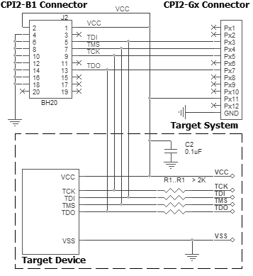
Connection for the Devices via 4-wire JTAG
Recommended connection:
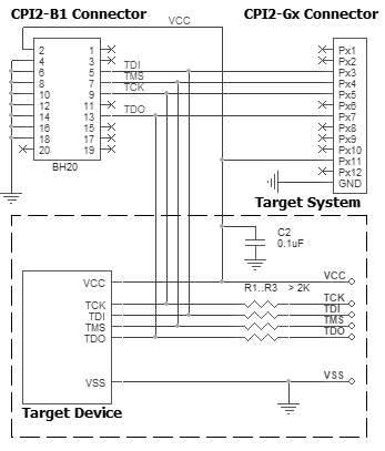
Powering the target device:
There are two alternative options for powering the targets:
1. The target gets power from the programmer (Vdd). This is possible only if the target does not consume too much energy. A capacity of the target power circuitry should not exceed 50 uF.
2. The target gets power from a built-in or external power supply. In this case the power output from the programmer should not be connected with the target. The target system should be tolerant to applying logical signals with the voltage levels exceeding the voltages on the target.
NOTE! It is strictly prohibited to power the target from both the programmer and built-in or external power supply simultaneously.
Isolating resistors:
Purpose of the resistors is to isolate the programmed chip from rest of target system. Recommended value of resistors is 2k or more. You can also use jumpers instead of the resistors.
ISP characteristics:
1. Programmer''s output capability:
1.1 Vcc - 80 mA with powering from USB and 350mA from external device programmer power supply;
1.2 Vpp - 50 mA;
1.3 logical pins - 5 mA.
2. The cable length should be less then one foot.
/Start is the input signal, active state is 0. This signal works as the Start button on the programmer.
/Error, /Good, /Busy are output logical signals, active state is 0. They indicate the programmer status and work as the corresponding LEDs on the programmer case.
Adapter Connection Table:
All power supply pins included AVdd must be powered. All ground pins included AVss must be connected together.
Connection for the Devices via 4-wire JTAG + Reset
Recommended connection:
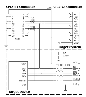
Powering the target device:
There are two alternative options for powering the targets:
1. The target gets power from the programmer (Vdd). This is possible only if the target does not consume too much energy. A capacity of the target power circuitry should not exceed 50 uF.
2. The target gets power from a built-in or external power supply. In this case the power output from the programmer should not be connected with the target. The target system should be tolerant to applying logical signals with the voltage levels exceeding the voltages on the target.
NOTE! It is strictly prohibited to power the target from both the programmer and built-in or external power supply simultaneously.
Isolating resistors:
Purpose of the resistors is to isolate the programmed chip from rest of target system. Recommended value of resistors is 2k or more. You can also use jumpers instead of the resistors.
ISP characteristics:
1. Programmer''s output capability:
1.1 Vcc - 80 mA with powering from USB and 350mA from external device programmer power supply;
1.2 Vpp - 50 mA;
1.3 logical pins - 5 mA.
2. The cable length should be less then one foot.
/Start is the input signal, active state is 0. This signal works as the Start button on the programmer.
/Error, /Good, /Busy are output logical signals, active state is 0. They indicate the programmer status and work as the corresponding LEDs on the programmer case.
Adapter Connection Table:
All power supply pins included AVdd must be powered. All ground pins included AVss must be connected together.
Connection for the Devices via 5-wire JTAG
Recommended connection:
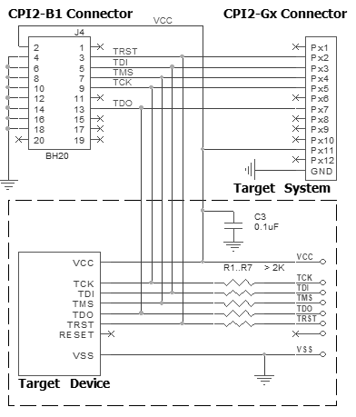
Powering the target device:
There are two alternative options for powering the targets:
1. The target gets power from the programmer (Vdd). This is possible only if the target does not consume too much energy. A capacity of the target power circuitry should not exceed 50 uF.
2. The target gets power from a built-in or external power supply. In this case the power output from the programmer should not be connected with the target. The target system should be tolerant to applying logical signals with the voltage levels exceeding the voltages on the target.
NOTE! It is strictly prohibited to power the target from both the programmer and built-in or external power supply simultaneously.
Isolating resistors:
Purpose of the resistors is to isolate the programmed chip from rest of target system. Recommended value of resistors is 2k or more. You can also use jumpers instead of the resistors.
ISP characteristics:
1. Programmer''s output capability:
1.1 Vcc - 80 mA with powering from USB and 350mA from external device programmer power supply;
1.2 Vpp - 50 mA;
1.3 logical pins - 5 mA.
2. The cable length should be less then one foot.
/Start is the input signal, active state is 0. This signal works as the Start button on the programmer.
/Error, /Good, /Busy are output logical signals, active state is 0. They indicate the programmer status and work as the corresponding LEDs on the programmer case.
Adapter Connection Table:
All power supply pins included AVdd must be powered. All ground pins included AVss must be connected together.
Connection for the Devices via 5-wire JTAG + Reset
Recommended connection:
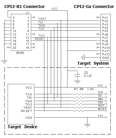
Powering the target device:
There are two alternative options for powering the targets:
1. The target gets power from the programmer (Vdd). This is possible only if the target does not consume too much energy. A capacity of the target power circuitry should not exceed 50 uF.
2. The target gets power from a built-in or external power supply. In this case the power output from the programmer should not be connected with the target. The target system should be tolerant to applying logical signals with the voltage levels exceeding the voltages on the target.
NOTE! It is strictly prohibited to power the target from both the programmer and built-in or external power supply simultaneously.
Isolating resistors:
Purpose of the resistors is to isolate the programmed chip from rest of target system. Recommended value of resistors is 2k or more. You can also use jumpers instead of the resistors.
ISP characteristics:
1. Programmer''s output capability:
1.1 Vcc - 80 mA with powering from USB and 350mA from external device programmer power supply;
1.2 Vpp - 50 mA;
1.3 logical pins - 5 mA.
2. The cable length should be less then one foot.
/Start is the input signal, active state is 0. This signal works as the Start button on the programmer.
/Error, /Good, /Busy are output logical signals, active state is 0. They indicate the programmer status and work as the corresponding LEDs on the programmer case.
Adapter Connection Table:
All power supply pins included AVdd must be powered. All ground pins included AVss must be connected together.
Connection for the Devices via SPI
Recommended connection:
Powering the target device:
There are two alternative options for powering the targets:
1. The target gets power from the programmer (Vdd). This is possible only if the target does not consume too much energy. A capacity of the target power circuitry should not exceed 50 uF.
2. The target gets power from a built-in or external power supply. In this case the power output from the programmer should not be connected with the target. The target system should be tolerant to applying logical signals with the voltage levels exceeding the voltages on the target.
NOTE! It is strictly prohibited to power the target from both the programmer and built-in or external power supply simultaneously.
Isolating resistors:
Purpose of the resistors is to isolate the programmed chip from rest of target system. Recommended value of resistors is 2k or more. You can also use jumpers instead of the resistors.
ISP characteristics:
1. Programmer''s output capability:
1.1 Vcc - 80 mA with powering from USB and 350mA from external device programmer power supply;
1.2 Vpp - 50 mA;
1.3 logical pins - 5 mA.
2. The cable length should be less then one foot.
/Start is the input signal, active state is 0. This signal works as the Start button on the programmer.
/Error, /Good, /Busy are output logical signals, active state is 0. They indicate the programmer status and work as the corresponding LEDs on the programmer case.
Adapter Connection Table:
Connection for the Devices with I2C, 1-Wire Interface
Recommended connection:
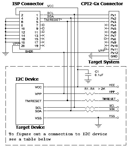
Powering the target device:
There are two alternative options for powering the targets:
1. The target gets power from the programmer (Vdd). This is possible only if the target does not consume too much energy. A capacity of the target power circuitry should not exceed 50 uF.
2. The target gets power from a built-in or external power supply. In this case the power output from the programmer should not be connected with the target. The target system should be tolerant to applying logical signals with the voltage levels exceeding the voltages on the target.
NOTE! It is strictly prohibited to power the target from both the programmer and built-in or external power supply simultaneously.
Isolating resistors:
Purpose of the resistors is to isolate the programmed chip from rest of target system. Recommended value of resistors is 2k or more. You can also use jumpers instead of the resistors.
ISP characteristics:
1. Programmer''s output capability:
1.1 Vcc - 80 mA with powering from USB and 350mA from external device programmer power supply;
1.2 Vpp - 50 mA;
1.3 logical pins - 5 mA.
2. The cable length should be less then one foot.
/Start is the input signal, active state is 0. This signal works as the Start button on the programmer.
/Error, /Good, /Busy are output logical signals, active state is 0. They indicate the programmer status and work as the corresponding LEDs on the programmer case.
Adapter Connection Table:
(1) - Power supply can be used for board supplying.
(2) - External pullup resistor is needed (3..3.9kOhm)
Connection for the Elmos E52x device
Recommended connection:
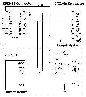
Powering the target device:
There are two alternative options for powering the targets:
1. The target gets power from the programmer (Vdd). This is possible only if the target does not consume too much energy. A capacity of the target power circuitry should not exceed 50 uF.
2. The target gets power from a built-in or external power supply. In this case the power output from the programmer should not be connected with the target. The target system should be tolerant to applying logical signals with the voltage levels exceeding the voltages on the target.
NOTE! It is strictly prohibited to power the target from both the programmer and built-in or external power supply simultaneously.
Isolating resistors:
Purpose of the resistors is to isolate the programmed chip from rest of target system. Recommended value of resistors is 2k or more. You can also use jumpers instead of the resistors.
ISP characteristics:
1. Programmer''s output capability:
1.1 VDD5 - 80 mA with powering from programmer;
1.2 logical pins - 5 mA.
2. The cable length should be less then one foot.
/Start is the input signal, active state is 0. This signal works as the Start button on the programmer.
/Error, /Good, /Busy are output logical signals, active state is 0. They indicate the programmer status and work as the corresponding LEDs on the programmer case.
Adapter Connection Table:
Connection for the Espressif ESP32 device
Recommended connection:
Powering the target device:
There are two alternative options for powering the targets:
1. The target gets power from the programmer (Vdd). This is possible only if the target does not consume too much energy. A capacity of the target power circuitry should not exceed 50 uF.
2. The target gets power from a built-in or external power supply. In this case the power output from the programmer should not be connected with the target. The target system should be tolerant to applying logical signals with the voltage levels exceeding the voltages on the target.
NOTE! It is strictly prohibited to power the target from both the programmer and built-in or external power supply simultaneously.
Isolating resistors:
Purpose of the resistors is to isolate the programmed chip from rest of target system. Recommended value of resistors is 2k or more. You can also use jumpers instead of the resistors.
ISP characteristics:
1. Programmer''s output capability:
1.1 Vcc - 80 mA with powering from USB and 350mA from external device programmer power supply;
1.2 Vpp - 50 mA;
1.3 logical pins - 5 mA.
2. The cable length should be less then one foot.
/Start is the input signal, active state is 0. This signal works as the Start button on the programmer.
/Error, /Good, /Busy are output logical signals, active state is 0. They indicate the programmer status and work as the corresponding LEDs on the programmer case.
Adapter Connection Table:
Connection for the FTDI FT900
Recommended connection:
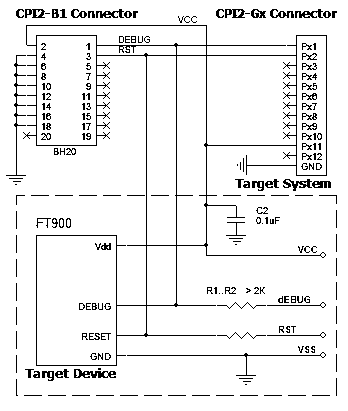
Powering the target device:
There are two alternative options for powering the targets:
1. The target gets power from the programmer (Vdd). This is possible only if the target does not consume too much energy. A capacity of the target power circuitry should not exceed 50 uF.
2. The target gets power from a built-in or external power supply. In this case the power output from the programmer should not be connected with the target. The target system should be tolerant to applying logical signals with the voltage levels exceeding the voltages on the target.
NOTE! It is strictly prohibited to power the target from both the programmer and built-in or external power supply simultaneously.
Isolating resistors:
Purpose of the resistors is to isolate the programmed chip from rest of target system. Recommended value of resistors is 2k or more. You can also use jumpers instead of the resistors.
ISP characteristics:
1. Programmer''s output capability:
1.1 Vcc - 80 mA with powering from USB and 350mA from external device programmer power supply;
1.2 Vpp - 50 mA;
1.3 logical pins - 5 mA.
2. The cable length should be less then one foot.
/Start is the input signal, active state is 0. This signal works as the Start button on the programmer.
/Error, /Good, /Busy are output logical signals, active state is 0. They indicate the programmer status and work as the corresponding LEDs on the programmer case.
Adapter Connection Table:
Connection for the Infineon SP37/SP40 devices
Recommended connection:
Powering the target device:
There are two alternative options for powering the targets:
1. The target gets power from the programmer (Vdd). This is possible only if the target does not consume too much energy. A capacity of the target power circuitry should not exceed 50 uF.
2. The target gets power from a built-in or external power supply. In this case the power output from the programmer should not be connected with the target. The target system should be tolerant to applying logical signals with the voltage levels exceeding the voltages on the target.
NOTE! It is strictly prohibited to power the target from both the programmer and built-in or external power supply simultaneously.
Isolating resistors:
Purpose of the resistors is to isolate the programmed chip from rest of target system. Recommended value of resistors is 2k or more. You can also use jumpers instead of the resistors.
ISP characteristics:
1. Programmer''s output capability:
1.1 Vcc - 80 mA with powering from USB and 350mA from external device programmer power supply;
1.2 Vpp - 50 mA;
1.3 logical pins - 5 mA.
2. The cable length should be less then one foot.
/Start is the input signal, active state is 0. This signal works as the Start button on the programmer.
/Error, /Good, /Busy are output logical signals, active state is 0. They indicate the programmer status and work as the corresponding LEDs on the programmer case.
Adapter Connection Table:
Connection for the Infineon TC2xx/TC3xx Devices
Recommended connection:
Powering the target device:
There are two alternative options for powering the targets:
1. The target gets power from the programmer (Vdd). This is possible only if the target does not consume too much energy. A capacity of the target power circuitry should not exceed 50 uF.
2. The target gets power from a built-in or external power supply. In this case the power output from the programmer should not be connected with the target. The target system should be tolerant to applying logical signals with the voltage levels exceeding the voltages on the target.
NOTE! It is strictly prohibited to power the target from both the programmer and built-in or external power supply simultaneously.
Isolating resistors:
Purpose of the resistors is to isolate the programmed chip from rest of target system. Recommended value of resistors is 2k or more. You can also use jumpers instead of the resistors.
ISP characteristics:
1. Programmer''s output capability:
1.1 Vcc - 80 mA with powering from USB and 350mA from external device programmer power supply;
1.2 Vpp - 50 mA;
1.3 logical pins - 5 mA.
2. The cable length should be less then one foot.
/Start is the input signal, active state is 0. This signal works as the Start button on the programmer.
/Error, /Good, /Busy are output logical signals, active state is 0. They indicate the programmer status and work as the corresponding LEDs on the programmer case.
Adapter Connection Table:
Connection for the Infineon XC886/888CLM devices
Recommended connection:
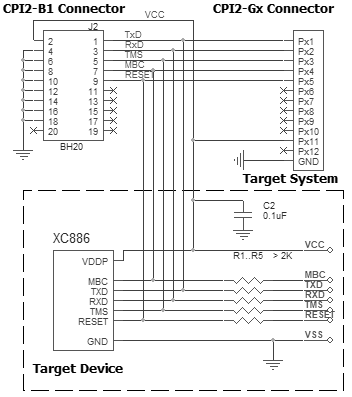
Powering the target device:
There are two alternative options for powering the targets:
1. The target gets power from the programmer (Vdd). This is possible only if the target does not consume too much energy. A capacity of the target power circuitry should not exceed 50 uF.
2. The target gets power from a built-in or external power supply. In this case the power output from the programmer should not be connected with the target. The target system should be tolerant to applying logical signals with the voltage levels exceeding the voltages on the target.
NOTE! It is strictly prohibited to power the target from both the programmer and built-in or external power supply simultaneously.
Isolating resistors:
Purpose of the resistors is to isolate the programmed chip from rest of target system. Recommended value of resistors is 2k or more. You can also use jumpers instead of the resistors.
ISP characteristics:
1. Programmer''s output capability:
1.1 Vcc - 80 mA with powering from USB and 350mA from external device programmer power supply;
1.2 Vpp - 50 mA;
1.3 logical pins - 5 mA.
2. The cable length should be less then one foot.
/Start is the input signal, active state is 0. This signal works as the Start button on the programmer.
/Error, /Good, /Busy are output logical signals, active state is 0. They indicate the programmer status and work as the corresponding LEDs on the programmer case.
Adapter Connection Table:
Connection for the LPC Flash and Firmware Hub
Recommended connection:
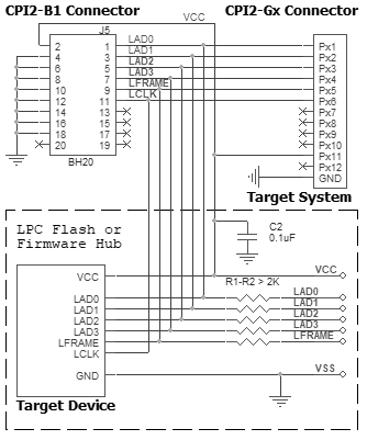
Powering the target device:
There are two alternative options for powering the targets:
1. The target gets power from the programmer (Vdd). This is possible only if the target does not consume too much energy. A capacity of the target power circuitry should not exceed 50 uF.
2. The target gets power from a built-in or external power supply. In this case the power output from the programmer should not be connected with the target. The target system should be tolerant to applying logical signals with the voltage levels exceeding the voltages on the target.
NOTE! It is strictly prohibited to power the target from both the programmer and built-in or external power supply simultaneously.
Isolating resistors:
Purpose of the resistors is to isolate the programmed chip from rest of target system. Recommended value of resistors is 2k or more. You can also use jumpers instead of the resistors.
ISP characteristics:
1. Programmer''s output capability:
1.1 Vcc - 80 mA with powering from USB and 350mA from external device programmer power supply;
1.2 Vpp - 50 mA;
1.3 logical pins - 5 mA.
2. The cable length should be less then one foot.
/Start is the input signal, active state is 0. This signal works as the Start button on the programmer.
/Error, /Good, /Busy are output logical signals, active state is 0. They indicate the programmer status and work as the corresponding LEDs on the programmer case.
Adapter Connection Table:
Connection for the Lattice ICE devices
Recommended connection:
Powering the target device:
There are two alternative options for powering the targets:
1. The target gets power from the programmer (Vdd). This is possible only if the target does not consume too much energy. A capacity of the target power circuitry should not exceed 50 uF.
2. The target gets power from a built-in or external power supply. In this case the power output from the programmer should not be connected with the target. The target system should be tolerant to applying logical signals with the voltage levels exceeding the voltages on the target.
NOTE! It is strictly prohibited to power the target from both the programmer and built-in or external power supply simultaneously.
Isolating resistors:
Purpose of the resistors is to isolate the programmed chip from rest of target system. Recommended value of resistors is 2k or more. You can also use jumpers instead of the resistors.
ISP characteristics:
1. Programmer''s output capability:
1.1 Vcc - 80 mA with powering from USB and 350mA from external device programmer power supply;
1.2 Vpp - 50 mA;
1.3 logical pins - 5 mA.
2. The cable length should be less then one foot.
/Start is the input signal, active state is 0. This signal works as the Start button on the programmer.
/Error, /Good, /Busy are output logical signals, active state is 0. They indicate the programmer status and work as the corresponding LEDs on the programmer case.
Adapter Connection Table:
Connection for the Microchip 34xx devices
Recommended connection:
Powering the target device:
There are two alternative options for powering the targets:
1. The target gets power from the programmer (Vdd). This is possible only if the target does not consume too much energy. A capacity of the target power circuitry should not exceed 50 uF.
2. The target gets power from a built-in or external power supply. In this case the power output from the programmer should not be connected with the target. The target system should be tolerant to applying logical signals with the voltage levels exceeding the voltages on the target.
NOTE! It is strictly prohibited to power the target from both the programmer and built-in or external power supply simultaneously.
Isolating resistors:
Purpose of the resistors is to isolate the programmed chip from rest of target system. Recommended value of resistors is 2k or more. You can also use jumpers instead of the resistors.
ISP characteristics:
1. Programmer''s output capability:
1.1 Vcc - 80 mA with powering from USB and 350mA from external device programmer power supply;
1.2 Vpp - 50 mA;
1.3 logical pins - 5 mA.
2. The cable length should be less then one foot.
/Start is the input signal, active state is 0. This signal works as the Start button on the programmer.
/Error, /Good, /Busy are output logical signals, active state is 0. They indicate the programmer status and work as the corresponding LEDs on the programmer case.
Adapter Connection Table:
Connection for the Microchip HCS101/HCS201/HCS360/HCS361/HCS362 devices
Recommended connection:
Powering the target device:
There are two alternative options for powering the targets:
1. The target gets power from the programmer (Vdd). This is possible only if the target does not consume too much energy. A capacity of the target power circuitry should not exceed 50 uF.
2. The target gets power from a built-in or external power supply. In this case the power output from the programmer should not be connected with the target. The target system should be tolerant to applying logical signals with the voltage levels exceeding the voltages on the target.
NOTE! It is strictly prohibited to power the target from both the programmer and built-in or external power supply simultaneously.
Isolating resistors:
Purpose of the resistors is to isolate the programmed chip from rest of target system. Recommended value of resistors is 2k or more. You can also use jumpers instead of the resistors.
ISP characteristics:
1. Programmer''s output capability:
1.1 Vcc - 80 mA with powering from USB and 350mA from external device programmer power supply;
1.2 Vpp - 50 mA;
1.3 logical pins - 5 mA.
2. The cable length should be less then one foot.
/Start is the input signal, active state is 0. This signal works as the Start button on the programmer.
/Error, /Good, /Busy are output logical signals, active state is 0. They indicate the programmer status and work as the corresponding LEDs on the programmer case.
Adapter Connection Table:
Connection for the Microchip HCS200/HCS300/HCS301/HCS320 devices
Recommended connection:
Powering the target device:
There are two alternative options for powering the targets:
1. The target gets power from the programmer (Vdd). This is possible only if the target does not consume too much energy. A capacity of the target power circuitry should not exceed 50 uF.
2. The target gets power from a built-in or external power supply. In this case the power output from the programmer should not be connected with the target. The target system should be tolerant to applying logical signals with the voltage levels exceeding the voltages on the target.
NOTE! It is strictly prohibited to power the target from both the programmer and built-in or external power supply simultaneously.
Isolating resistors:
Purpose of the resistors is to isolate the programmed chip from rest of target system. Recommended value of resistors is 2k or more. You can also use jumpers instead of the resistors.
ISP characteristics:
1. Programmer''s output capability:
1.1 Vcc - 80 mA with powering from USB and 350mA from external device programmer power supply;
1.2 Vpp - 50 mA;
1.3 logical pins - 5 mA.
2. The cable length should be less then one foot.
/Start is the input signal, active state is 0. This signal works as the Start button on the programmer.
/Error, /Good, /Busy are output logical signals, active state is 0. They indicate the programmer status and work as the corresponding LEDs on the programmer case.
Adapter Connection Table:
Connection for the Microchip MCP250XX devices
Recommended connection:
Powering the target device:
There are two alternative options for powering the targets:
1. The target gets power from the programmer (Vdd). This is possible only if the target does not consume too much energy. A capacity of the target power circuitry should not exceed 50 uF.
2. The target gets power from a built-in or external power supply. In this case the power output from the programmer should not be connected with the target. The target system should be tolerant to applying logical signals with the voltage levels exceeding the voltages on the target.
NOTE! It is strictly prohibited to power the target from both the programmer and built-in or external power supply simultaneously.
Isolating resistors:
Purpose of the resistors is to isolate the programmed chip from rest of target system. Recommended value of resistors is 2k or more. You can also use jumpers instead of the resistors.
ISP characteristics:
1. Programmer''s output capability:
1.1 Vcc - 80 mA with powering from USB and 350mA from external device programmer power supply;
1.2 Vpp - 50 mA;
1.3 logical pins - 5 mA.
2. The cable length should be less then one foot.
/Start is the input signal, active state is 0. This signal works as the Start button on the programmer.
/Error, /Good, /Busy are output logical signals, active state is 0. They indicate the programmer status and work as the corresponding LEDs on the programmer case.
Adapter Connection Table:
Connection for the Microchip PIC10/PIC12 devices
Recommended connection:
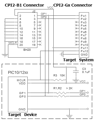
Powering the target device:
There are two alternative options for powering the targets:
1. The target gets power from the programmer (Vdd). This is possible only if the target does not consume too much energy. A capacity of the target power circuitry should not exceed 50 uF.
2. The target gets power from a built-in or external power supply. In this case the power output from the programmer should not be connected with the target. The target system should be tolerant to applying logical signals with the voltage levels exceeding the voltages on the target.
NOTE! It is strictly prohibited to power the target from both the programmer and built-in or external power supply simultaneously.
Isolating resistors:
Purpose of the resistors is to isolate the programmed chip from rest of target system. Recommended value of resistors is 2k or more. You can also use jumpers instead of the resistors.
ISP characteristics:
1. Programmer''s output capability:
1.1 Vcc - 80 mA with powering from USB and 350mA from external device programmer power supply;
1.2 Vpp - 50 mA;
1.3 logical pins - 5 mA.
2. The cable length should be less then one foot.
/Start is the input signal, active state is 0. This signal works as the Start button on the programmer.
/Error, /Good, /Busy are output logical signals, active state is 0. They indicate the programmer status and work as the corresponding LEDs on the programmer case.
Adapter Connection Table:
All power supply pins included AVdd must be powered. All ground pins included AVss must be connected together.
Connection for the Microchip PIC16/PIC18 devices
Recommended connection:
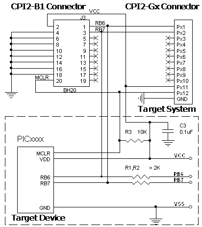
Powering the target device:
There are two alternative options for powering the targets:
1. The target gets power from the programmer (Vdd). This is possible only if the target does not consume too much energy. A capacity of the target power circuitry should not exceed 50 uF.
2. The target gets power from a built-in or external power supply. In this case the power output from the programmer should not be connected with the target. The target system should be tolerant to applying logical signals with the voltage levels exceeding the voltages on the target.
NOTE! It is strictly prohibited to power the target from both the programmer and built-in or external power supply simultaneously.
Isolating resistors:
Purpose of the resistors is to isolate the programmed chip from rest of target system. Recommended value of resistors is 2k or more. You can also use jumpers instead of the resistors.
ISP characteristics:
1. Programmer''s output capability:
1.1 Vcc - 80 mA with powering from USB and 350mA from external device programmer power supply;
1.2 Vpp - 50 mA;
1.3 logical pins - 5 mA.
2. The cable length should be less then one foot.
/Start is the input signal, active state is 0. This signal works as the Start button on the programmer.
/Error, /Good, /Busy are output logical signals, active state is 0. They indicate the programmer status and work as the corresponding LEDs on the programmer case.
Adapter Connection Table:
All power supply pins included AVdd must be powered. All ground pins included AVss must be connected together.
Connection for the Microchip PIC16C505 devices
Recommended connection:
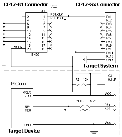
Powering the target device:
There are two alternative options for powering the targets:
1. The target gets power from the programmer (Vdd). This is possible only if the target does not consume too much energy. A capacity of the target power circuitry should not exceed 50 uF.
2. The target gets power from a built-in or external power supply. In this case the power output from the programmer should not be connected with the target. The target system should be tolerant to applying logical signals with the voltage levels exceeding the voltages on the target.
NOTE! It is strictly prohibited to power the target from both the programmer and built-in or external power supply simultaneously.
Isolating resistors:
Purpose of the resistors is to isolate the programmed chip from rest of target system. Recommended value of resistors is 2k or more. You can also use jumpers instead of the resistors.
ISP characteristics:
1. Programmer''s output capability:
1.1 Vcc - 80 mA with powering from USB and 350mA from external device programmer power supply;
1.2 Vpp - 50 mA;
1.3 logical pins - 5 mA.
2. The cable length should be less then one foot.
/Start is the input signal, active state is 0. This signal works as the Start button on the programmer.
/Error, /Good, /Busy are output logical signals, active state is 0. They indicate the programmer status and work as the corresponding LEDs on the programmer case.
Adapter Connection Table:
All power supply pins included AVdd must be powered. All ground pins included AVss must be connected together.
Connection for the Microchip PIC16Fxxx 14pin devices
Recommended connection:
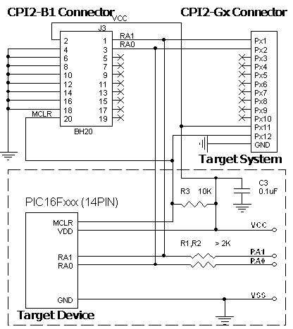
Powering the target device:
There are two alternative options for powering the targets:
1. The target gets power from the programmer (Vdd). This is possible only if the target does not consume too much energy. A capacity of the target power circuitry should not exceed 50 uF.
2. The target gets power from a built-in or external power supply. In this case the power output from the programmer should not be connected with the target. The target system should be tolerant to applying logical signals with the voltage levels exceeding the voltages on the target.
NOTE! It is strictly prohibited to power the target from both the programmer and built-in or external power supply simultaneously.
Isolating resistors:
Purpose of the resistors is to isolate the programmed chip from rest of target system. Recommended value of resistors is 2k or more. You can also use jumpers instead of the resistors.
ISP characteristics:
1. Programmer''s output capability:
1.1 Vcc - 80 mA with powering from USB and 350mA from external device programmer power supply;
1.2 Vpp - 50 mA;
1.3 logical pins - 5 mA.
2. The cable length should be less then one foot.
/Start is the input signal, active state is 0. This signal works as the Start button on the programmer.
/Error, /Good, /Busy are output logical signals, active state is 0. They indicate the programmer status and work as the corresponding LEDs on the programmer case.
Adapter Connection Table:
Connection for the Microchip PIC18FxxJ devices
Recommended connection:
Powering the target device:
There are two alternative options for powering the targets:
1. The target gets power from the programmer (Vdd). This is possible only if the target does not consume too much energy. A capacity of the target power circuitry should not exceed 50 uF.
2. The target gets power from a built-in or external power supply. In this case the power output from the programmer should not be connected with the target. The target system should be tolerant to applying logical signals with the voltage levels exceeding the voltages on the target.
NOTE! It is strictly prohibited to power the target from both the programmer and built-in or external power supply simultaneously.
Isolating resistors:
Purpose of the resistors is to isolate the programmed chip from rest of target system. Recommended value of resistors is 2k or more. You can also use jumpers instead of the resistors.
ISP characteristics:
1. Programmer''s output capability:
1.1 Vcc - 80 mA with powering from USB and 350mA from external device programmer power supply;
1.2 Vpp - 50 mA;
1.3 logical pins - 5 mA.
2. The cable length should be less then one foot.
/Start is the input signal, active state is 0. This signal works as the Start button on the programmer.
/Error, /Good, /Busy are output logical signals, active state is 0. They indicate the programmer status and work as the corresponding LEDs on the programmer case.
Adapter Connection Table:
All power supply pins included AVdd must be powered. All ground pins included AVss must be connected together.
Connection for the Microchip PIC24 devices
Recommended connection:
Powering the target device:
There are two alternative options for powering the targets:
1. The target gets power from the programmer (Vdd). This is possible only if the target does not consume too much energy. A capacity of the target power circuitry should not exceed 50 uF.
2. The target gets power from a built-in or external power supply. In this case the power output from the programmer should not be connected with the target. The target system should be tolerant to applying logical signals with the voltage levels exceeding the voltages on the target.
NOTE! It is strictly prohibited to power the target from both the programmer and built-in or external power supply simultaneously.
Isolating resistors:
Purpose of the resistors is to isolate the programmed chip from rest of target system. Recommended value of resistors is 2k or more. You can also use jumpers instead of the resistors.
ISP characteristics:
1. Programmer''s output capability:
1.1 Vcc - 80 mA with powering from USB and 350mA from external device programmer power supply;
1.2 Vpp - 50 mA;
1.3 logical pins - 5 mA.
2. The cable length should be less then one foot.
/Start is the input signal, active state is 0. This signal works as the Start button on the programmer.
/Error, /Good, /Busy are output logical signals, active state is 0. They indicate the programmer status and work as the corresponding LEDs on the programmer case.
Adapter Connection Table:
All power supply pins included AVdd must be powered. All ground pins included AVss must be connected together.
Connection for the Microchip PIC24FxxxKA devices
Recommended connection:
Powering the target device:
There are two alternative options for powering the targets:
1. The target gets power from the programmer (Vdd). This is possible only if the target does not consume too much energy. A capacity of the target power circuitry should not exceed 50 uF.
2. The target gets power from a built-in or external power supply. In this case the power output from the programmer should not be connected with the target. The target system should be tolerant to applying logical signals with the voltage levels exceeding the voltages on the target.
NOTE! It is strictly prohibited to power the target from both the programmer and built-in or external power supply simultaneously.
Isolating resistors:
Purpose of the resistors is to isolate the programmed chip from rest of target system. Recommended value of resistors is 2k or more. You can also use jumpers instead of the resistors.
ISP characteristics:
1. Programmer''s output capability:
1.1 Vcc - 80 mA with powering from USB and 350mA from external device programmer power supply;
1.2 Vpp - 50 mA;
1.3 logical pins - 5 mA.
2. The cable length should be less then one foot.
/Start is the input signal, active state is 0. This signal works as the Start button on the programmer.
/Error, /Good, /Busy are output logical signals, active state is 0. They indicate the programmer status and work as the corresponding LEDs on the programmer case.
Adapter Connection Table:
All power supply pins included AVdd must be powered. All ground pins included AVss must be connected together.
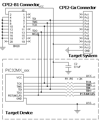
Connection for the Microchip PIC32xx devices via ICSP
Recommended connection:
Powering the target device:
There are two alternative options for powering the targets:
1. The target gets power from the programmer (Vdd). This is possible only if the target does not consume too much energy. A capacity of the target power circuitry should not exceed 50 uF.
2. The target gets power from a built-in or external power supply. In this case the power output from the programmer should not be connected with the target. The target system should be tolerant to applying logical signals with the voltage levels exceeding the voltages on the target.
NOTE! It is strictly prohibited to power the target from both the programmer and built-in or external power supply simultaneously.
Isolating resistors:
Purpose of the resistors is to isolate the programmed chip from rest of target system. Recommended value of resistors is 2k or more. You can also use jumpers instead of the resistors.
ISP characteristics:
1. Programmer''s output capability:
1.1 Vcc - 80 mA with powering from USB and 350mA from external device programmer power supply;
1.2 Vpp - 50 mA;
1.3 logical pins - 5 mA.
2. The cable length should be less then one foot.
/Start is the input signal, active state is 0. This signal works as the Start button on the programmer.
/Error, /Good, /Busy are output logical signals, active state is 0. They indicate the programmer status and work as the corresponding LEDs on the programmer case.
Adapter Connection Table:
All power supply pins included AVdd must be powered. All ground pins included AVss must be connected together.
Connection for the Microchip PIC32xx devices via JTAG
Recommended connection:
Powering the target device:
There are two alternative options for powering the targets:
1. The target gets power from the programmer (Vdd). This is possible only if the target does not consume too much energy. A capacity of the target power circuitry should not exceed 50 uF.
2. The target gets power from a built-in or external power supply. In this case the power output from the programmer should not be connected with the target. The target system should be tolerant to applying logical signals with the voltage levels exceeding the voltages on the target.
NOTE! It is strictly prohibited to power the target from both the programmer and built-in or external power supply simultaneously.
Isolating resistors:
Purpose of the resistors is to isolate the programmed chip from rest of target system. Recommended value of resistors is 2k or more. You can also use jumpers instead of the resistors.
ISP characteristics:
1. Programmer''s output capability:
1.1 Vcc - 80 mA with powering from USB and 350mA from external device programmer power supply;
1.2 Vpp - 50 mA;
1.3 logical pins - 5 mA.
2. The cable length should be less then one foot.
/Start is the input signal, active state is 0. This signal works as the Start button on the programmer.
/Error, /Good, /Busy are output logical signals, active state is 0. They indicate the programmer status and work as the corresponding LEDs on the programmer case.
Adapter Connection Table:
All power supply pins included AVdd must be powered. All ground pins included AVss must be connected together.
Connection for the Microchip dsPIC30F devices
Recommended connection:
Powering the target device:
There are two alternative options for powering the targets:
1. The target gets power from the programmer (Vdd). This is possible only if the target does not consume too much energy. A capacity of the target power circuitry should not exceed 50 uF.
2. The target gets power from a built-in or external power supply. In this case the power output from the programmer should not be connected with the target. The target system should be tolerant to applying logical signals with the voltage levels exceeding the voltages on the target.
NOTE! It is strictly prohibited to power the target from both the programmer and built-in or external power supply simultaneously.
Isolating resistors:
Purpose of the resistors is to isolate the programmed chip from rest of target system. Recommended value of resistors is 2k or more. You can also use jumpers instead of the resistors.
ISP characteristics:
1. Programmer''s output capability:
1.1 Vcc - 80 mA with powering from USB and 350mA from external device programmer power supply;
1.2 Vpp - 50 mA;
1.3 logical pins - 5 mA.
2. The cable length should be less then one foot.
/Start is the input signal, active state is 0. This signal works as the Start button on the programmer.
/Error, /Good, /Busy are output logical signals, active state is 0. They indicate the programmer status and work as the corresponding LEDs on the programmer case.
Adapter Connection Table:
All power supply pins included AVdd must be powered. All ground pins included AVss must be connected together.
Connection for the Microchip dsPIC33 devices
Recommended connection:
Powering the target device:
There are two alternative options for powering the targets:
1. The target gets power from the programmer (Vdd). This is possible only if the target does not consume too much energy. A capacity of the target power circuitry should not exceed 50 uF.
2. The target gets power from a built-in or external power supply. In this case the power output from the programmer should not be connected with the target. The target system should be tolerant to applying logical signals with the voltage levels exceeding the voltages on the target.
NOTE! It is strictly prohibited to power the target from both the programmer and built-in or external power supply simultaneously.
Isolating resistors:
Purpose of the resistors is to isolate the programmed chip from rest of target system. Recommended value of resistors is 2k or more. You can also use jumpers instead of the resistors.
ISP characteristics:
1. Programmer''s output capability:
1.1 Vcc - 80 mA with powering from USB and 350mA from external device programmer power supply;
1.2 Vpp - 50 mA;
1.3 logical pins - 5 mA.
2. The cable length should be less then one foot.
/Start is the input signal, active state is 0. This signal works as the Start button on the programmer.
/Error, /Good, /Busy are output logical signals, active state is 0. They indicate the programmer status and work as the corresponding LEDs on the programmer case.
Adapter Connection Table:
All power supply pins included AVdd must be powered. All ground pins included AVss must be connected together.
Connection for the Microchip/Atmel AT89LPxxx devices
Recommended connection:
Powering the target device:
There are two alternative options for powering the targets:
1. The target gets power from the programmer (Vdd). This is possible only if the target does not consume too much energy. A capacity of the target power circuitry should not exceed 50 uF.
2. The target gets power from a built-in or external power supply. In this case the power output from the programmer should not be connected with the target. The target system should be tolerant to applying logical signals with the voltage levels exceeding the voltages on the target.
NOTE! It is strictly prohibited to power the target from both the programmer and built-in or external power supply simultaneously.
Isolating resistors:
Purpose of the resistors is to isolate the programmed chip from rest of target system. Recommended value of resistors is 2k or more. You can also use jumpers instead of the resistors.
ISP characteristics:
1. Programmer''s output capability:
1.1 Vcc - 80 mA with powering from USB and 350mA from external device programmer power supply;
1.2 Vpp - 50 mA;
1.3 logical pins - 5 mA.
2. The cable length should be less then one foot.
/Start is the input signal, active state is 0. This signal works as the Start button on the programmer.
/Error, /Good, /Busy are output logical signals, active state is 0. They indicate the programmer status and work as the corresponding LEDs on the programmer case.
Adapter Connection Table:
Connection for the Microchip/Atmel AT90/ATS89S/ATtiny/ATmega devices
Recommended connection:
Powering the target device:
There are two alternative options for powering the targets:
1. The target gets power from the programmer (Vdd). This is possible only if the target does not consume too much energy. A capacity of the target power circuitry should not exceed 50 uF.
2. The target gets power from a built-in or external power supply. In this case the power output from the programmer should not be connected with the target. The target system should be tolerant to applying logical signals with the voltage levels exceeding the voltages on the target.
NOTE! It is strictly prohibited to power the target from both the programmer and built-in or external power supply simultaneously.
Isolating resistors:
Purpose of the resistors is to isolate the programmed chip from rest of target system. Recommended value of resistors is 2k or more. You can also use jumpers instead of the resistors.
ISP characteristics:
1. Programmer''s output capability:
1.1 Vcc - 80 mA with powering from USB and 350mA from external device programmer power supply;
1.2 Vpp - 50 mA;
1.3 logical pins - 5 mA.
2. The cable length should be less then one foot.
/Start is the input signal, active state is 0. This signal works as the Start button on the programmer.
/Error, /Good, /Busy are output logical signals, active state is 0. They indicate the programmer status and work as the corresponding LEDs on the programmer case.
Adapter Connection Table:
* Must be connected if there is no external oscillator in system.
Connection for the Microchip/Atmel ATtiny devices in the High-Voltage mode
Recommended connection:
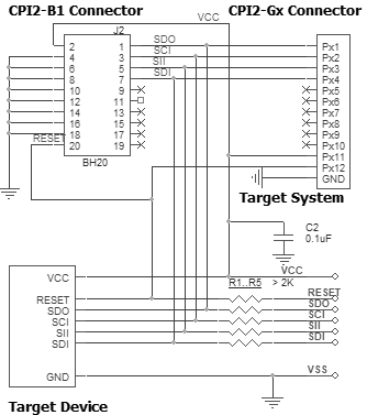
Powering the target device:
There are two alternative options for powering the targets:
1. The target gets power from the programmer (Vdd). This is possible only if the target does not consume too much energy. A capacity of the target power circuitry should not exceed 50 uF.
2. The target gets power from a built-in or external power supply. In this case the power output from the programmer should not be connected with the target. The target system should be tolerant to applying logical signals with the voltage levels exceeding the voltages on the target.
NOTE! It is strictly prohibited to power the target from both the programmer and built-in or external power supply simultaneously.
Isolating resistors:
Purpose of the resistors is to isolate the programmed chip from rest of target system. Recommended value of resistors is 2k or more. You can also use jumpers instead of the resistors.
ISP characteristics:
1. Programmer''s output capability:
1.1 Vcc - 80 mA with powering from USB and 350mA from external device programmer power supply;
1.2 Vpp - 50 mA;
1.3 logical pins - 5 mA.
2. The cable length should be less then one foot.
/Start is the input signal, active state is 0. This signal works as the Start button on the programmer.
/Error, /Good, /Busy are output logical signals, active state is 0. They indicate the programmer status and work as the corresponding LEDs on the programmer case.
Adapter Connection Table:
Connection for the Microchip/Atmel ATtiny devices in the UPDI mode
Recommended connection:
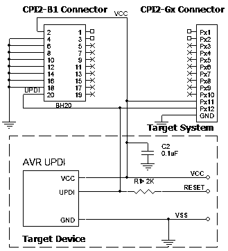
Powering the target device:
There are two alternative options for powering the targets:
1. The target gets power from the programmer (Vdd). This is possible only if the target does not consume too much energy. A capacity of the target power circuitry should not exceed 50 uF.
2. The target gets power from a built-in or external power supply. In this case the power output from the programmer should not be connected with the target. The target system should be tolerant to applying logical signals with the voltage levels exceeding the voltages on the target.
NOTE! It is strictly prohibited to power the target from both the programmer and built-in or external power supply simultaneously.
Isolating resistors:
Purpose of the resistors is to isolate the programmed chip from rest of target system. Recommended value of resistors is 2k or more. You can also use jumpers instead of the resistors.
ISP characteristics:
1. Programmer''s output capability:
1.1 Vcc - 80 mA with powering from USB and 350mA from external device programmer power supply;
1.2 Vpp - 50 mA;
1.3 logical pins - 5 mA.
2. The cable length should be less then one foot.
/Start is the input signal, active state is 0. This signal works as the Start button on the programmer.
/Error, /Good, /Busy are output logical signals, active state is 0. They indicate the programmer status and work as the corresponding LEDs on the programmer case.
Adapter Connection Table:
Connection for the Microchip/Atmel Atmel ATmega103/128/1281/2561 AT90CAN128 devices
Recommended connection:
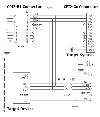
Powering the target device:
There are two alternative options for powering the targets:
1. The target gets power from the programmer (Vdd). This is possible only if the target does not consume too much energy. A capacity of the target power circuitry should not exceed 50 uF.
2. The target gets power from a built-in or external power supply. In this case the power output from the programmer should not be connected with the target. The target system should be tolerant to applying logical signals with the voltage levels exceeding the voltages on the target.
NOTE! It is strictly prohibited to power the target from both the programmer and built-in or external power supply simultaneously.
Isolating resistors:
Purpose of the resistors is to isolate the programmed chip from rest of target system. Recommended value of resistors is 2k or more. You can also use jumpers instead of the resistors.
ISP characteristics:
1. Programmer''s output capability:
1.1 Vcc - 80 mA with powering from USB and 350mA from external device programmer power supply;
1.2 Vpp - 50 mA;
1.3 logical pins - 5 mA.
2. The cable length should be less then one foot.
/Start is the input signal, active state is 0. This signal works as the Start button on the programmer.
/Error, /Good, /Busy are output logical signals, active state is 0. They indicate the programmer status and work as the corresponding LEDs on the programmer case.
Adapter Connection Table:
* Must be connected if there is no external oscillator in system.
Connection for the Microchip/Atmel devices in PDI/TPI mode
Recommended connection:
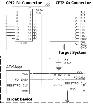
Powering the target device:
There are two alternative options for powering the targets:
1. The target gets power from the programmer (Vdd). This is possible only if the target does not consume too much energy. A capacity of the target power circuitry should not exceed 50 uF.
2. The target gets power from a built-in or external power supply. In this case the power output from the programmer should not be connected with the target. The target system should be tolerant to applying logical signals with the voltage levels exceeding the voltages on the target.
NOTE! It is strictly prohibited to power the target from both the programmer and built-in or external power supply simultaneously.
Isolating resistors:
Purpose of the resistors is to isolate the programmed chip from rest of target system. Recommended value of resistors is 2k or more. You can also use jumpers instead of the resistors.
ISP characteristics:
1. Programmer''s output capability:
1.1 Vcc - 80 mA with powering from USB and 350mA from external device programmer power supply;
1.2 Vpp - 50 mA;
1.3 logical pins - 5 mA.
2. The cable length should be less then one foot.
/Start is the input signal, active state is 0. This signal works as the Start button on the programmer.
/Error, /Good, /Busy are output logical signals, active state is 0. They indicate the programmer status and work as the corresponding LEDs on the programmer case.
Adapter Connection Table:
Connection for the NEC UPD78F9210, UPD78F9211 devices
Recommended connection:
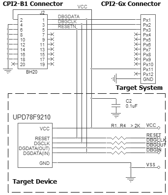
Powering the target device:
There are two alternative options for powering the targets:
1. The target gets power from the programmer (Vdd). This is possible only if the target does not consume too much energy. A capacity of the target power circuitry should not exceed 50 uF.
2. The target gets power from a built-in or external power supply. In this case the power output from the programmer should not be connected with the target. The target system should be tolerant to applying logical signals with the voltage levels exceeding the voltages on the target.
NOTE! It is strictly prohibited to power the target from both the programmer and built-in or external power supply simultaneously.
Isolating resistors:
Purpose of the resistors is to isolate the programmed chip from rest of target system. Recommended value of resistors is 2k or more. You can also use jumpers instead of the resistors.
ISP characteristics:
1. Programmer''s output capability:
1.1 Vcc - 80 mA with powering from USB and 350mA from external device programmer power supply;
1.2 Vpp - 50 mA;
1.3 logical pins - 5 mA.
2. The cable length should be less then one foot.
/Start is the input signal, active state is 0. This signal works as the Start button on the programmer.
/Error, /Good, /Busy are output logical signals, active state is 0. They indicate the programmer status and work as the corresponding LEDs on the programmer case.
Adapter Connection Table:
Connection for the NEC devices in SPI mode
Recommended connection:
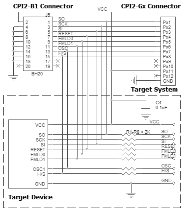
Powering the target device:
There are two alternative options for powering the targets:
1. The target gets power from the programmer (Vdd). This is possible only if the target does not consume too much energy. A capacity of the target power circuitry should not exceed 50 uF.
2. The target gets power from a built-in or external power supply. In this case the power output from the programmer should not be connected with the target. The target system should be tolerant to applying logical signals with the voltage levels exceeding the voltages on the target.
NOTE! It is strictly prohibited to power the target from both the programmer and built-in or external power supply simultaneously.
Isolating resistors:
Purpose of the resistors is to isolate the programmed chip from rest of target system. Recommended value of resistors is 2k or more. You can also use jumpers instead of the resistors.
ISP characteristics:
1. Programmer''s output capability:
1.1 Vcc - 80 mA with powering from USB and 350mA from external device programmer power supply;
1.2 Vpp - 50 mA;
1.3 logical pins - 5 mA.
2. The cable length should be less then one foot.
/Start is the input signal, active state is 0. This signal works as the Start button on the programmer.
/Error, /Good, /Busy are output logical signals, active state is 0. They indicate the programmer status and work as the corresponding LEDs on the programmer case.
Adapter Connection Table:
Connection for the NEC devices in UART mode
Recommended connection:
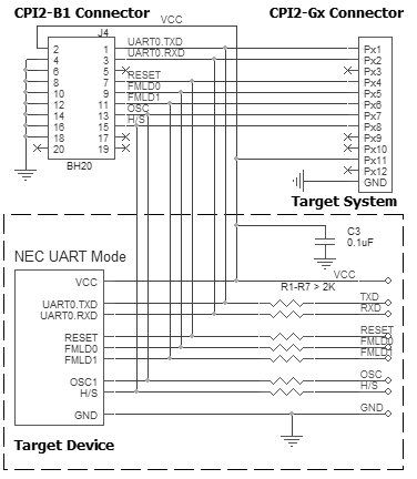
Powering the target device:
There are two alternative options for powering the targets:
1. The target gets power from the programmer (Vdd). This is possible only if the target does not consume too much energy. A capacity of the target power circuitry should not exceed 50 uF.
2. The target gets power from a built-in or external power supply. In this case the power output from the programmer should not be connected with the target. The target system should be tolerant to applying logical signals with the voltage levels exceeding the voltages on the target.
NOTE! It is strictly prohibited to power the target from both the programmer and built-in or external power supply simultaneously.
Isolating resistors:
Purpose of the resistors is to isolate the programmed chip from rest of target system. Recommended value of resistors is 2k or more. You can also use jumpers instead of the resistors.
ISP characteristics:
1. Programmer''s output capability:
1.1 Vcc - 80 mA with powering from USB and 350mA from external device programmer power supply;
1.2 Vpp - 50 mA;
1.3 logical pins - 5 mA.
2. The cable length should be less then one foot.
/Start is the input signal, active state is 0. This signal works as the Start button on the programmer.
/Error, /Good, /Busy are output logical signals, active state is 0. They indicate the programmer status and work as the corresponding LEDs on the programmer case.
Adapter Connection Table:
Connection for the NEC devices in one-wire UART mode
Recommended connection:
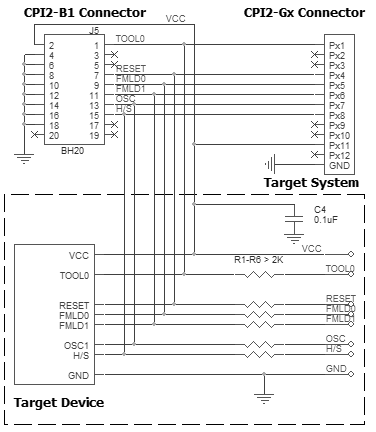
Powering the target device:
There are two alternative options for powering the targets:
1. The target gets power from the programmer (Vdd). This is possible only if the target does not consume too much energy. A capacity of the target power circuitry should not exceed 50 uF.
2. The target gets power from a built-in or external power supply. In this case the power output from the programmer should not be connected with the target. The target system should be tolerant to applying logical signals with the voltage levels exceeding the voltages on the target.
NOTE! It is strictly prohibited to power the target from both the programmer and built-in or external power supply simultaneously.
Isolating resistors:
Purpose of the resistors is to isolate the programmed chip from rest of target system. Recommended value of resistors is 2k or more. You can also use jumpers instead of the resistors.
ISP characteristics:
1. Programmer''s output capability:
1.1 Vcc - 80 mA with powering from USB and 350mA from external device programmer power supply;
1.2 Vpp - 50 mA;
1.3 logical pins - 5 mA.
2. The cable length should be less then one foot.
/Start is the input signal, active state is 0. This signal works as the Start button on the programmer.
/Error, /Good, /Busy are output logical signals, active state is 0. They indicate the programmer status and work as the corresponding LEDs on the programmer case.
Adapter Connection Table:
Connection for the NIIET 1882BE53Y devices
Recommended connection:
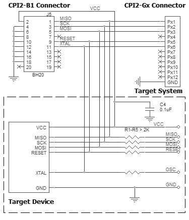
Powering the target device:
There are two alternative options for powering the targets:
1. The target gets power from the programmer (Vdd). This is possible only if the target does not consume too much energy. A capacity of the target power circuitry should not exceed 50 uF.
2. The target gets power from a built-in or external power supply. In this case the power output from the programmer should not be connected with the target. The target system should be tolerant to applying logical signals with the voltage levels exceeding the voltages on the target.
NOTE! It is strictly prohibited to power the target from both the programmer and built-in or external power supply simultaneously.
Isolating resistors:
Purpose of the resistors is to isolate the programmed chip from rest of target system. Recommended value of resistors is 2k or more. You can also use jumpers instead of the resistors.
ISP characteristics:
1. Programmer''s output capability:
1.1 Vcc - 80 mA with powering from USB and 350mA from external device programmer power supply;
1.2 Vpp - 50 mA;
1.3 logical pins - 5 mA.
2. The cable length should be less then one foot.
/Start is the input signal, active state is 0. This signal works as the Start button on the programmer.
/Error, /Good, /Busy are output logical signals, active state is 0. They indicate the programmer status and work as the corresponding LEDs on the programmer case.
Adapter Connection Table:
* Must be connected if there is no external oscillator in system.
Connection for the NVM3060 device
Recommended connection:
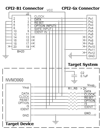
Powering the target device:
There are two alternative options for powering the targets:
1. The target gets power from the programmer (Vdd). This is possible only if the target does not consume too much energy. A capacity of the target power circuitry should not exceed 50 uF.
2. The target gets power from a built-in or external power supply. In this case the power output from the programmer should not be connected with the target. The target system should be tolerant to applying logical signals with the voltage levels exceeding the voltages on the target.
NOTE! It is strictly prohibited to power the target from both the programmer and built-in or external power supply simultaneously.
Isolating resistors:
Purpose of the resistors is to isolate the programmed chip from rest of target system. Recommended value of resistors is 2k or more. You can also use jumpers instead of the resistors.
ISP characteristics:
1. Programmer''s output capability:
1.1 Vcc - 80 mA with powering from USB and 350mA from external device programmer power supply;
1.2 Vpp - 50 mA;
1.3 logical pins - 5 mA.
2. The cable length should be less then one foot.
/Start is the input signal, active state is 0. This signal works as the Start button on the programmer.
/Error, /Good, /Busy are output logical signals, active state is 0. They indicate the programmer status and work as the corresponding LEDs on the programmer case.
Adapter Connection Table:
Connection for the NXP JN51XX.
Recommended connection:
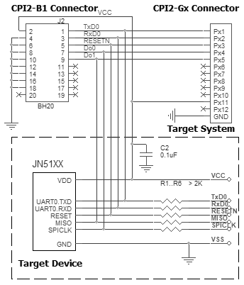
Powering the target device:
There are two alternative options for powering the targets:
1. The target gets power from the programmer (Vdd). This is possible only if the target does not consume too much energy. A capacity of the target power circuitry should not exceed 50 uF.
2. The target gets power from a built-in or external power supply. In this case the power output from the programmer should not be connected with the target. The target system should be tolerant to applying logical signals with the voltage levels exceeding the voltages on the target.
NOTE! It is strictly prohibited to power the target from both the programmer and built-in or external power supply simultaneously.
Isolating resistors:
Purpose of the resistors is to isolate the programmed chip from rest of target system. Recommended value of resistors is 2k or more. You can also use jumpers instead of the resistors.
ISP characteristics:
1. Programmer''s output capability:
1.1 Vcc - 80 mA with powering from USB and 350mA from external device programmer power supply;
1.2 Vpp - 50 mA;
1.3 logical pins - 5 mA.
2. The cable length should be less then one foot.
/Start is the input signal, active state is 0. This signal works as the Start button on the programmer.
/Error, /Good, /Busy are output logical signals, active state is 0. They indicate the programmer status and work as the corresponding LEDs on the programmer case.
Adapter Connection Table:
Connection for the NXP PCF79xx devices
Recommended connection:
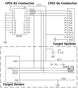
Powering the target device:
There is only one option for powering the targets:
1. The target gets power from the programmer (Vdd). This is possible only if the target does not consume too much energy. A capacity of the target power circuitry should not exceed 50 uF.
Isolating resistors:
Purpose of the resistors is to isolate the programmed chip from rest of target system. Recommended value of resistors is 2k or more. You can also use jumpers instead of the resistors.
ISP characteristics:
1. Programmer''s output capability:
1.1 Vcc - 80 mA with powering from USB and 350mA from external device programmer power supply;
1.2 Vpp - 50 mA;
1.3 logical pins - 5 mA.
2. The cable length should be less then one foot.
/Start is the input signal, active state is 0. This signal works as the Start button on the programmer.
/Error, /Good, /Busy are output logical signals, active state is 0. They indicate the programmer status and work as the corresponding LEDs on the programmer case.
Adapter Connection Table:
Connection for the NXP QN9080 microcontrollers via SWD
Recommended connection:
Powering the target device:
There are two alternative options for powering the targets:
1. The target gets power from the programmer (Vdd). This is possible only if the target does not consume too much energy. A capacity of the target power circuitry should not exceed 50 uF.
2. The target gets power from a built-in or external power supply. In this case the power output from the programmer should not be connected with the target. The target system should be tolerant to applying logical signals with the voltage levels exceeding the voltages on the target.
NOTE! It is strictly prohibited to power the target from both the programmer and built-in or external power supply simultaneously.
Isolating resistors:
Purpose of the resistors is to isolate the programmed chip from rest of target system. Recommended value of resistors is 2k or more. You can also use jumpers instead of the resistors.
ISP characteristics:
1. Programmer''s output capability:
1.1 Vcc - 80 mA with powering from USB and 350mA from external device programmer power supply;
1.2 Vpp - 50 mA;
1.3 logical pins - 5 mA.
2. The cable length should be less then one foot.
/Start is the input signal, active state is 0. This signal works as the Start button on the programmer.
/Error, /Good, /Busy are output logical signals, active state is 0. They indicate the programmer status and work as the corresponding LEDs on the programmer case.
Adapter Connection Table:
All power supply pins included AVdd must be powered. All ground pins included AVss must be connected together.
Connection for the NXP/Freescale 9RS08xx devices
Recommended connection:
Powering the target device:
There are two alternative options for powering the targets:
1. The target gets power from the programmer (Vdd). This is possible only if the target does not consume too much energy. A capacity of the target power circuitry should not exceed 50 uF.
2. The target gets power from a built-in or external power supply. In this case the power output from the programmer should not be connected with the target. The target system should be tolerant to applying logical signals with the voltage levels exceeding the voltages on the target.
NOTE! It is strictly prohibited to power the target from both the programmer and built-in or external power supply simultaneously.
Isolating resistors:
Purpose of the resistors is to isolate the programmed chip from rest of target system. Recommended value of resistors is 2k or more. You can also use jumpers instead of the resistors.
ISP characteristics:
1. Programmer''s output capability:
1.1 Vcc - 80 mA with powering from USB and 350mA from external device programmer power supply;
1.2 Vpp - 50 mA;
1.3 logical pins - 5 mA.
2. The cable length should be less then one foot.
/Start is the input signal, active state is 0. This signal works as the Start button on the programmer.
/Error, /Good, /Busy are output logical signals, active state is 0. They indicate the programmer status and work as the corresponding LEDs on the programmer case.
Adapter Connection Table:
Connection for the NXP/Freescale HCS08, HCS12 devices
Recommended connection:
Powering the target device:
There are two alternative options for powering the targets:
1. The target gets power from the programmer (Vdd). This is possible only if the target does not consume too much energy. A capacity of the target power circuitry should not exceed 50 uF.
2. The target gets power from a built-in or external power supply. In this case the power output from the programmer should not be connected with the target. The target system should be tolerant to applying logical signals with the voltage levels exceeding the voltages on the target.
NOTE! It is strictly prohibited to power the target from both the programmer and built-in or external power supply simultaneously.
Isolating resistors:
Purpose of the resistors is to isolate the programmed chip from rest of target system. Recommended value of resistors is 2k or more. You can also use jumpers instead of the resistors.
ISP characteristics:
1. Programmer''s output capability:
1.1 Vcc - 80 mA with powering from USB and 350mA from external device programmer power supply;
1.2 Vpp - 50 mA;
1.3 logical pins - 5 mA.
2. The cable length should be less then one foot.
/Start is the input signal, active state is 0. This signal works as the Start button on the programmer.
/Error, /Good, /Busy are output logical signals, active state is 0. They indicate the programmer status and work as the corresponding LEDs on the programmer case.
Adapter Connection Table:
Connection for the NXP/Freescale Kinetis microcontrollers via EzPort
Recommended connection:
Powering the target device:
There are two alternative options for powering the targets:
1. The target gets power from the programmer (Vdd). This is possible only if the target does not consume too much energy. A capacity of the target power circuitry should not exceed 50 uF.
2. The target gets power from a built-in or external power supply. In this case the power output from the programmer should not be connected with the target. The target system should be tolerant to applying logical signals with the voltage levels exceeding the voltages on the target.
NOTE! It is strictly prohibited to power the target from both the programmer and built-in or external power supply simultaneously.
Isolating resistors:
Purpose of the resistors is to isolate the programmed chip from rest of target system. Recommended value of resistors is 2k or more. You can also use jumpers instead of the resistors.
ISP characteristics:
1. Programmer''s output capability:
1.1 Vcc - 80 mA with powering from USB and 350mA from external device programmer power supply;
1.2 Vpp - 50 mA;
1.3 logical pins - 5 mA.
2. The cable length should be less then one foot.
/Start is the input signal, active state is 0. This signal works as the Start button on the programmer.
/Error, /Good, /Busy are output logical signals, active state is 0. They indicate the programmer status and work as the corresponding LEDs on the programmer case.
Adapter Connection Table:
All power supply pins included AVdd must be powered. All ground pins included AVss must be connected together.
Connection for the NXP/Freescale MC68HC908 devices
Recommended connection:
Powering the target device:
There are two alternative options for powering the targets:
1. The target gets power from the programmer (Vdd). This is possible only if the target does not consume too much energy. A capacity of the target power circuitry should not exceed 50 uF.
2. The target gets power from a built-in or external power supply. In this case the power output from the programmer should not be connected with the target. The target system should be tolerant to applying logical signals with the voltage levels exceeding the voltages on the target.
NOTE! It is strictly prohibited to power the target from both the programmer and built-in or external power supply simultaneously.
Isolating resistors:
Purpose of the resistors is to isolate the programmed chip from rest of target system. Recommended value of resistors is 2k or more. You can also use jumpers instead of the resistors.
ISP characteristics:
1. Programmer''s output capability:
1.1 Vcc - 80 mA with powering from USB and 350mA from external device programmer power supply;
1.2 Vpp - 50 mA;
1.3 logical pins - 5 mA.
2. The cable length should be less then one foot.
/Start is the input signal, active state is 0. This signal works as the Start button on the programmer.
/Error, /Good, /Busy are output logical signals, active state is 0. They indicate the programmer status and work as the corresponding LEDs on the programmer case.
Adapter Connection Table:
* Must be connected if there is no external oscillator in system.
Connection for the NXP/Philips LPC1100/LPC1300 devices in the BSL Mode
Recommended connection:
Powering the target device:
There are two alternative options for powering the targets:
1. The target gets power from the programmer (Vdd). This is possible only if the target does not consume too much energy. A capacity of the target power circuitry should not exceed 50 uF.
2. The target gets power from a built-in or external power supply. In this case the power output from the programmer should not be connected with the target. The target system should be tolerant to applying logical signals with the voltage levels exceeding the voltages on the target.
NOTE! It is strictly prohibited to power the target from both the programmer and built-in or external power supply simultaneously.
Isolating resistors:
Purpose of the resistors is to isolate the programmed chip from rest of target system. Recommended value of resistors is 2k or more. You can also use jumpers instead of the resistors.
ISP characteristics:
1. Programmer''s output capability:
1.1 Vcc - 80 mA with powering from USB and 350mA from external device programmer power supply;
1.2 Vpp - 50 mA;
1.3 logical pins - 5 mA.
2. The cable length should be less then one foot.
/Start is the input signal, active state is 0. This signal works as the Start button on the programmer.
/Error, /Good, /Busy are output logical signals, active state is 0. They indicate the programmer status and work as the corresponding LEDs on the programmer case.
Adapter Connection Table:
Connection for the NXP/Philips LPC1700/LPC2300/LPC2400 devices in the BSL Mode
Recommended connection:
Powering the target device:
There are two alternative options for powering the targets:
1. The target gets power from the programmer (Vdd). This is possible only if the target does not consume too much energy. A capacity of the target power circuitry should not exceed 50 uF.
2. The target gets power from a built-in or external power supply. In this case the power output from the programmer should not be connected with the target. The target system should be tolerant to applying logical signals with the voltage levels exceeding the voltages on the target.
NOTE! It is strictly prohibited to power the target from both the programmer and built-in or external power supply simultaneously.
Isolating resistors:
Purpose of the resistors is to isolate the programmed chip from rest of target system. Recommended value of resistors is 2k or more. You can also use jumpers instead of the resistors.
ISP characteristics:
1. Programmer''s output capability:
1.1 Vcc - 80 mA with powering from USB and 350mA from external device programmer power supply;
1.2 Vpp - 50 mA;
1.3 logical pins - 5 mA.
2. The cable length should be less then one foot.
/Start is the input signal, active state is 0. This signal works as the Start button on the programmer.
/Error, /Good, /Busy are output logical signals, active state is 0. They indicate the programmer status and work as the corresponding LEDs on the programmer case.
Adapter Connection Table:
Connection for the NXP/Philips LPC2100/LPC2200 devices in the BSL Mode
Recommended connection:
Powering the target device:
There are two alternative options for powering the targets:
1. The target gets power from the programmer (Vdd). This is possible only if the target does not consume too much energy. A capacity of the target power circuitry should not exceed 50 uF.
2. The target gets power from a built-in or external power supply. In this case the power output from the programmer should not be connected with the target. The target system should be tolerant to applying logical signals with the voltage levels exceeding the voltages on the target.
NOTE! It is strictly prohibited to power the target from both the programmer and built-in or external power supply simultaneously.
Isolating resistors:
Purpose of the resistors is to isolate the programmed chip from rest of target system. Recommended value of resistors is 2k or more. You can also use jumpers instead of the resistors.
ISP characteristics:
1. Programmer''s output capability:
1.1 Vcc - 80 mA with powering from USB and 350mA from external device programmer power supply;
1.2 Vpp - 50 mA;
1.3 logical pins - 5 mA.
2. The cable length should be less then one foot.
/Start is the input signal, active state is 0. This signal works as the Start button on the programmer.
/Error, /Good, /Busy are output logical signals, active state is 0. They indicate the programmer status and work as the corresponding LEDs on the programmer case.
Adapter Connection Table:
* Must be connected if there is no external oscillator in system.
Connection for the NXP/Philips P89LPC9xx devices in the ISP Mode
Recommended connection:
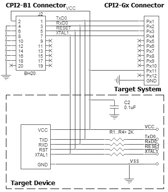
Powering the target device:
There are two alternative options for powering the targets:
1. The target gets power from the programmer (Vdd). This is possible only if the target does not consume too much energy. A capacity of the target power circuitry should not exceed 50 uF.
2. The target gets power from a built-in or external power supply. In this case the power output from the programmer should not be connected with the target. The target system should be tolerant to applying logical signals with the voltage levels exceeding the voltages on the target.
NOTE! It is strictly prohibited to power the target from both the programmer and built-in or external power supply simultaneously.
Isolating resistors:
Purpose of the resistors is to isolate the programmed chip from rest of target system. Recommended value of resistors is 2k or more. You can also use jumpers instead of the resistors.
ISP characteristics:
1. Programmer''s output capability:
1.1 Vcc - 80 mA with powering from USB and 350mA from external device programmer power supply;
1.2 Vpp - 50 mA;
1.3 logical pins - 5 mA.
2. The cable length should be less then one foot.
/Start is the input signal, active state is 0. This signal works as the Start button on the programmer.
/Error, /Good, /Busy are output logical signals, active state is 0. They indicate the programmer status and work as the corresponding LEDs on the programmer case.
Adapter Connection Table:
Connection for the NXP/Philips P89xxx devices in the ICP Mode
Recommended connection:
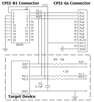
Powering the target device:
There are two alternative options for powering the targets:
1. The target gets power from the programmer (Vdd). This is possible only if the target does not consume too much energy. A capacity of the target power circuitry should not exceed 50 uF.
2. The target gets power from a built-in or external power supply. In this case the power output from the programmer should not be connected with the target. The target system should be tolerant to applying logical signals with the voltage levels exceeding the voltages on the target.
NOTE! It is strictly prohibited to power the target from both the programmer and built-in or external power supply simultaneously.
Isolating resistors:
Purpose of the resistors is to isolate the programmed chip from rest of target system. Recommended value of resistors is 2k or more. You can also use jumpers instead of the resistors.
ISP characteristics:
1. Programmer''s output capability:
1.1 Vcc - 80 mA with powering from USB and 350mA from external device programmer power supply;
1.2 Vpp - 50 mA;
1.3 logical pins - 5 mA.
2. The cable length should be less then one foot.
/Start is the input signal, active state is 0. This signal works as the Start button on the programmer.
/Error, /Good, /Busy are output logical signals, active state is 0. They indicate the programmer status and work as the corresponding LEDs on the programmer case.
Adapter Connection Table:
Connection for the Nordic nRF24xxx OTP microcontrollers
Recommended connection:
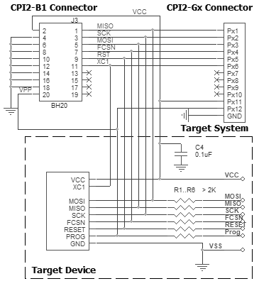
Powering the target device:
There are two alternative options for powering the targets:
1. The target gets power from the programmer (Vdd). This is possible only if the target does not consume too much energy. A capacity of the target power circuitry should not exceed 50 uF.
2. The target gets power from a built-in or external power supply. In this case the power output from the programmer should not be connected with the target. The target system should be tolerant to applying logical signals with the voltage levels exceeding the voltages on the target.
NOTE! It is strictly prohibited to power the target from both the programmer and built-in or external power supply simultaneously.
Isolating resistors:
Purpose of the resistors is to isolate the programmed chip from rest of target system. Recommended value of resistors is 2k or more. You can also use jumpers instead of the resistors.
ISP characteristics:
1. Programmer''s output capability:
1.1 Vcc - 80 mA with powering from USB and 350mA from external device programmer power supply;
1.2 Vpp - 50 mA;
1.3 logical pins - 5 mA.
2. The cable length should be less then one foot.
/Start is the input signal, active state is 0. This signal works as the Start button on the programmer.
/Error, /Good, /Busy are output logical signals, active state is 0. They indicate the programmer status and work as the corresponding LEDs on the programmer case.
Adapter Connection Table:
* Must be connected if there is no external oscillator in system.
Connection for the Nordic nRF24xxx microcontrollers
Recommended connection:
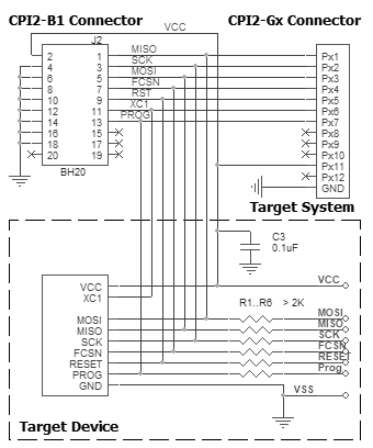
Powering the target device:
There are two alternative options for powering the targets:
1. The target gets power from the programmer (Vdd). This is possible only if the target does not consume too much energy. A capacity of the target power circuitry should not exceed 50 uF.
2. The target gets power from a built-in or external power supply. In this case the power output from the programmer should not be connected with the target. The target system should be tolerant to applying logical signals with the voltage levels exceeding the voltages on the target.
NOTE! It is strictly prohibited to power the target from both the programmer and built-in or external power supply simultaneously.
Isolating resistors:
Purpose of the resistors is to isolate the programmed chip from rest of target system. Recommended value of resistors is 2k or more. You can also use jumpers instead of the resistors.
ISP characteristics:
1. Programmer''s output capability:
1.1 Vcc - 80 mA with powering from USB and 350mA from external device programmer power supply;
1.2 Vpp - 50 mA;
1.3 logical pins - 5 mA.
2. The cable length should be less then one foot.
/Start is the input signal, active state is 0. This signal works as the Start button on the programmer.
/Error, /Good, /Busy are output logical signals, active state is 0. They indicate the programmer status and work as the corresponding LEDs on the programmer case.
Adapter Connection Table:
* Must be connected if there is no external oscillator in system.
Connection for the Nuvoton ISD2xxx
Recommended connection:
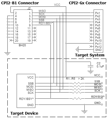
Powering the target device:
There are two alternative options for powering the targets:
1. The target gets power from the programmer (Vdd). This is possible only if the target does not consume too much energy. A capacity of the target power circuitry should not exceed 50 uF.
2. The target gets power from a built-in or external power supply. In this case the power output from the programmer should not be connected with the target. The target system should be tolerant to applying logical signals with the voltage levels exceeding the voltages on the target.
NOTE! It is strictly prohibited to power the target from both the programmer and built-in or external power supply simultaneously.
Isolating resistors:
Purpose of the resistors is to isolate the programmed chip from rest of target system. Recommended value of resistors is 2k or more. You can also use jumpers instead of the resistors.
ISP characteristics:
1. Programmer''s output capability:
1.1 Vcc - 80 mA with powering from USB and 350mA from external device programmer power supply;
1.2 Vpp - 50 mA;
1.3 logical pins - 5 mA.
2. The cable length should be less then one foot.
/Start is the input signal, active state is 0. This signal works as the Start button on the programmer.
/Error, /Good, /Busy are output logical signals, active state is 0. They indicate the programmer status and work as the corresponding LEDs on the programmer case.
Adapter Connection Table:
Connection for the Renesas Cortex microcontrollers via UART
Recommended connection:
Powering the target device:
There are two alternative options for powering the targets:
1. The target gets power from the programmer (Vdd). This is possible only if the target does not consume too much energy. A capacity of the target power circuitry should not exceed 50 uF.
2. The target gets power from a built-in or external power supply. In this case the power output from the programmer should not be connected with the target. The target system should be tolerant to applying logical signals with the voltage levels exceeding the voltages on the target.
NOTE! It is strictly prohibited to power the target from both the programmer and built-in or external power supply simultaneously.
Isolating resistors:
Purpose of the resistors is to isolate the programmed chip from rest of target system. Recommended value of resistors is 2k or more. You can also use jumpers instead of the resistors.
ISP characteristics:
1. Programmer''s output capability:
1.1 Vcc - 80 mA with powering from USB and 350mA from external device programmer power supply;
1.2 Vpp - 50 mA;
1.3 logical pins - 5 mA.
2. The cable length should be less then one foot.
/Start is the input signal, active state is 0. This signal works as the Start button on the programmer.
/Error, /Good, /Busy are output logical signals, active state is 0. They indicate the programmer status and work as the corresponding LEDs on the programmer case.
Adapter Connection Table:
All power supply pins included AVdd must be powered. All ground pins included AVss must be connected together.
Connection for the Renesas R8C devices in the 1-wire UART Mode
Recommended connection:
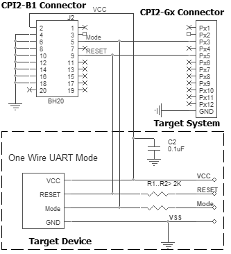
Powering the target device:
There are two alternative options for powering the targets:
1. The target gets power from the programmer (Vdd). This is possible only if the target does not consume too much energy. A capacity of the target power circuitry should not exceed 50 uF.
2. The target gets power from a built-in or external power supply. In this case the power output from the programmer should not be connected with the target. The target system should be tolerant to applying logical signals with the voltage levels exceeding the voltages on the target.
NOTE! It is strictly prohibited to power the target from both the programmer and built-in or external power supply simultaneously.
Isolating resistors:
Purpose of the resistors is to isolate the programmed chip from rest of target system. Recommended value of resistors is 2k or more. You can also use jumpers instead of the resistors.
ISP characteristics:
1. Programmer''s output capability:
1.1 Vcc - 80 mA with powering from USB and 350mA from external device programmer power supply;
1.2 Vpp - 50 mA;
1.3 logical pins - 5 mA.
2. The cable length should be less then one foot.
/Start is the input signal, active state is 0. This signal works as the Start button on the programmer.
/Error, /Good, /Busy are output logical signals, active state is 0. They indicate the programmer status and work as the corresponding LEDs on the programmer case.
Adapter Connection Table:
Connection for the Renesas R8C devices in the UART Mode
Recommended connection:
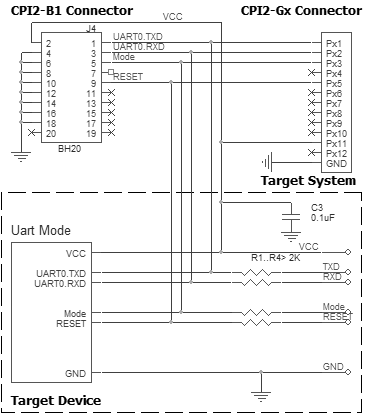
Powering the target device:
There are two alternative options for powering the targets:
1. The target gets power from the programmer (Vdd). This is possible only if the target does not consume too much energy. A capacity of the target power circuitry should not exceed 50 uF.
2. The target gets power from a built-in or external power supply. In this case the power output from the programmer should not be connected with the target. The target system should be tolerant to applying logical signals with the voltage levels exceeding the voltages on the target.
NOTE! It is strictly prohibited to power the target from both the programmer and built-in or external power supply simultaneously.
Isolating resistors:
Purpose of the resistors is to isolate the programmed chip from rest of target system. Recommended value of resistors is 2k or more. You can also use jumpers instead of the resistors.
ISP characteristics:
1. Programmer''s output capability:
1.1 Vcc - 80 mA with powering from USB and 350mA from external device programmer power supply;
1.2 Vpp - 50 mA;
1.3 logical pins - 5 mA.
2. The cable length should be less then one foot.
/Start is the input signal, active state is 0. This signal works as the Start button on the programmer.
/Error, /Good, /Busy are output logical signals, active state is 0. They indicate the programmer status and work as the corresponding LEDs on the programmer case.
Adapter Connection Table:
* Must be connected if there is no external oscillator in system.
Connection for the Renesas RH850 devices in 1-wire UART Mode
Recommended connection:
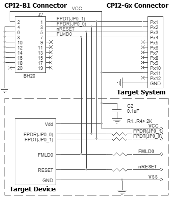
Powering the target device:
There are two alternative options for powering the targets:
1. The target gets power from the programmer (Vdd). This is possible only if the target does not consume too much energy. A capacity of the target power circuitry should not exceed 50 uF.
2. The target gets power from a built-in or external power supply. In this case the power output from the programmer should not be connected with the target. The target system should be tolerant to applying logical signals with the voltage levels exceeding the voltages on the target.
NOTE! It is strictly prohibited to power the target from both the programmer and built-in or external power supply simultaneously.
Isolating resistors:
Purpose of the resistors is to isolate the programmed chip from rest of target system. Recommended value of resistors is 2k or more. You can also use jumpers instead of the resistors.
ISP characteristics:
1. Programmer''s output capability:
1.1 Vcc - 80 mA with powering from USB and 350mA from external device programmer power supply;
1.2 Vpp - 50 mA;
1.3 logical pins - 5 mA.
2. The cable length should be less then one foot.
/Start is the input signal, active state is 0. This signal works as the Start button on the programmer.
/Error, /Good, /Busy are output logical signals, active state is 0. They indicate the programmer status and work as the corresponding LEDs on the programmer case.
Adapter Connection Table:
Connection for the Renesas RH850 devices in 2-wire UART Mode
Recommended connection:
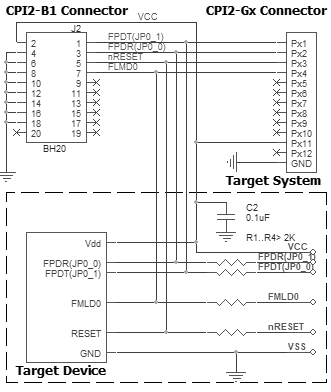
Powering the target device:
There are two alternative options for powering the targets:
1. The target gets power from the programmer (Vdd). This is possible only if the target does not consume too much energy. A capacity of the target power circuitry should not exceed 50 uF.
2. The target gets power from a built-in or external power supply. In this case the power output from the programmer should not be connected with the target. The target system should be tolerant to applying logical signals with the voltage levels exceeding the voltages on the target.
NOTE! It is strictly prohibited to power the target from both the programmer and built-in or external power supply simultaneously.
Isolating resistors:
Purpose of the resistors is to isolate the programmed chip from rest of target system. Recommended value of resistors is 2k or more. You can also use jumpers instead of the resistors.
ISP characteristics:
1. Programmer''s output capability:
1.1 Vcc - 80 mA with powering from USB and 350mA from external device programmer power supply;
1.2 Vpp - 50 mA;
1.3 logical pins - 5 mA.
2. The cable length should be less then one foot.
/Start is the input signal, active state is 0. This signal works as the Start button on the programmer.
/Error, /Good, /Busy are output logical signals, active state is 0. They indicate the programmer status and work as the corresponding LEDs on the programmer case.
Adapter Connection Table:
Connection for the Renesas RH850 devices in CSI Mode
Recommended connection:
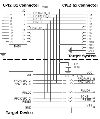
Powering the target device:
There are two alternative options for powering the targets:
1. The target gets power from the programmer (Vdd). This is possible only if the target does not consume too much energy. A capacity of the target power circuitry should not exceed 50 uF.
2. The target gets power from a built-in or external power supply. In this case the power output from the programmer should not be connected with the target. The target system should be tolerant to applying logical signals with the voltage levels exceeding the voltages on the target.
NOTE! It is strictly prohibited to power the target from both the programmer and built-in or external power supply simultaneously.
Isolating resistors:
Purpose of the resistors is to isolate the programmed chip from rest of target system. Recommended value of resistors is 2k or more. You can also use jumpers instead of the resistors.
ISP characteristics:
1. Programmer''s output capability:
1.1 Vcc - 80 mA with powering from USB and 350mA from external device programmer power supply;
1.2 Vpp - 50 mA;
1.3 logical pins - 5 mA.
2. The cable length should be less then one foot.
/Start is the input signal, active state is 0. This signal works as the Start button on the programmer.
/Error, /Good, /Busy are output logical signals, active state is 0. They indicate the programmer status and work as the corresponding LEDs on the programmer case.
Adapter Connection Table:
Connection for the Renesas RL78xx devices
Recommended connection:
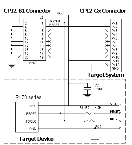
Powering the target device:
There are two alternative options for powering the targets:
1. The target gets power from the programmer (Vdd). This is possible only if the target does not consume too much energy. A capacity of the target power circuitry should not exceed 50 uF.
2. The target gets power from a built-in or external power supply. In this case the power output from the programmer should not be connected with the target. The target system should be tolerant to applying logical signals with the voltage levels exceeding the voltages on the target.
NOTE! It is strictly prohibited to power the target from both the programmer and built-in or external power supply simultaneously.
Isolating resistors:
Purpose of the resistors is to isolate the programmed chip from rest of target system. Recommended value of resistors is 2k or more. You can also use jumpers instead of the resistors.
ISP characteristics:
1. Programmer''s output capability:
1.1 Vcc - 80 mA with powering from USB and 350mA from external device programmer power supply;
1.2 Vpp - 50 mA;
1.3 logical pins - 5 mA.
2. The cable length should be less then one foot.
/Start is the input signal, active state is 0. This signal works as the Start button on the programmer.
/Error, /Good, /Busy are output logical signals, active state is 0. They indicate the programmer status and work as the corresponding LEDs on the programmer case.
Adapter Connection Table:
Connection for the Renesas RX series microcontrollers via FINE
Recommended connection:
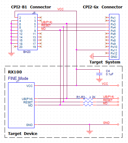
Powering the target device:
There are two alternative options for powering the targets:
1. The target gets power from the programmer (Vdd). This is possible only if the target does not consume too much energy. A capacity of the target power circuitry should not exceed 50 uF.
2. The target gets power from a built-in or external power supply. In this case the power output from the programmer should not be connected with the target. The target system should be tolerant to applying logical signals with the voltage levels exceeding the voltages on the target.
NOTE! It is strictly prohibited to power the target from both the programmer and built-in or external power supply simultaneously.
Isolating resistors:
Purpose of the resistors is to isolate the programmed chip from rest of target system. Recommended value of resistors is 2k or more. You can also use jumpers instead of the resistors.
ISP characteristics:
1. Programmer''s output capability:
1.1 Vcc - 80 mA with powering from USB and 350mA from external device programmer power supply;
1.2 Vpp - 50 mA;
1.3 logical pins - 5 mA.
2. The cable length should be less then one foot.
/Start is the input signal, active state is 0. This signal works as the Start button on the programmer.
/Error, /Good, /Busy are output logical signals, active state is 0. They indicate the programmer status and work as the corresponding LEDs on the programmer case.
Adapter Connection Table:
Connection for the Renesas RX series microcontrollers via UART
Recommended connection:
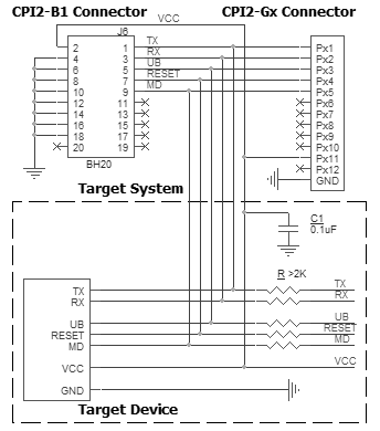
Powering the target device:
There are two alternative options for powering the targets:
1. The target gets power from the programmer (Vdd). This is possible only if the target does not consume too much energy. A capacity of the target power circuitry should not exceed 50 uF.
2. The target gets power from a built-in or external power supply. In this case the power output from the programmer should not be connected with the target. The target system should be tolerant to applying logical signals with the voltage levels exceeding the voltages on the target.
NOTE! It is strictly prohibited to power the target from both the programmer and built-in or external power supply simultaneously.
Isolating resistors:
Purpose of the resistors is to isolate the programmed chip from rest of target system. Recommended value of resistors is 2k or more. You can also use jumpers instead of the resistors.
ISP characteristics:
1. Programmer''s output capability:
1.1 Vcc - 80 mA with powering from USB and 350mA from external device programmer power supply;
1.2 Vpp - 50 mA;
1.3 logical pins - 5 mA.
2. The cable length should be less then one foot.
/Start is the input signal, active state is 0. This signal works as the Start button on the programmer.
/Error, /Good, /Busy are output logical signals, active state is 0. They indicate the programmer status and work as the corresponding LEDs on the programmer case.
Adapter Connection Table:
Connection for the Renesas V850 devices in CSI Mode
Recommended connection:
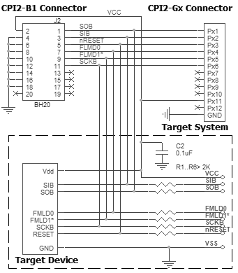
Powering the target device:
There are two alternative options for powering the targets:
1. The target gets power from the programmer (Vdd). This is possible only if the target does not consume too much energy. A capacity of the target power circuitry should not exceed 50 uF.
2. The target gets power from a built-in or external power supply. In this case the power output from the programmer should not be connected with the target. The target system should be tolerant to applying logical signals with the voltage levels exceeding the voltages on the target.
NOTE! It is strictly prohibited to power the target from both the programmer and built-in or external power supply simultaneously.
Isolating resistors:
Purpose of the resistors is to isolate the programmed chip from rest of target system. Recommended value of resistors is 2k or more. You can also use jumpers instead of the resistors.
ISP characteristics:
1. Programmer''s output capability:
1.1 Vcc - 80 mA with powering from USB and 350mA from external device programmer power supply;
1.2 Vpp - 50 mA;
1.3 logical pins - 5 mA.
2. The cable length should be less then one foot.
/Start is the input signal, active state is 0. This signal works as the Start button on the programmer.
/Error, /Good, /Busy are output logical signals, active state is 0. They indicate the programmer status and work as the corresponding LEDs on the programmer case.
Adapter Connection Table:
FLMD1* for programming mode must be tied to GND. If it''s tied on a target board, this signal can be not connected to programmer.
Connection for the Renesas V850 devices in CSI+HS Mode
Recommended connection:
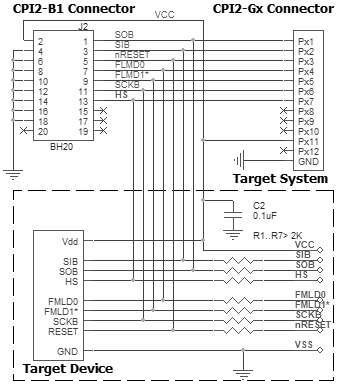
Powering the target device:
There are two alternative options for powering the targets:
1. The target gets power from the programmer (Vdd). This is possible only if the target does not consume too much energy. A capacity of the target power circuitry should not exceed 50 uF.
2. The target gets power from a built-in or external power supply. In this case the power output from the programmer should not be connected with the target. The target system should be tolerant to applying logical signals with the voltage levels exceeding the voltages on the target.
NOTE! It is strictly prohibited to power the target from both the programmer and built-in or external power supply simultaneously.
Isolating resistors:
Purpose of the resistors is to isolate the programmed chip from rest of target system. Recommended value of resistors is 2k or more. You can also use jumpers instead of the resistors.
ISP characteristics:
1. Programmer''s output capability:
1.1 Vcc - 80 mA with powering from USB and 350mA from external device programmer power supply;
1.2 Vpp - 50 mA;
1.3 logical pins - 5 mA.
2. The cable length should be less then one foot.
/Start is the input signal, active state is 0. This signal works as the Start button on the programmer.
/Error, /Good, /Busy are output logical signals, active state is 0. They indicate the programmer status and work as the corresponding LEDs on the programmer case.
Adapter Connection Table:
FLMD1* for programming mode must be tied to GND. If it''s tied on a target board, this signal can be not connected to programmer.
Connection for the Renesas V850 devices in UART Mode
Recommended connection:
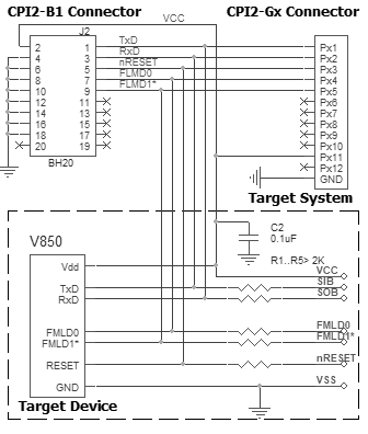
Powering the target device:
There are two alternative options for powering the targets:
1. The target gets power from the programmer (Vdd). This is possible only if the target does not consume too much energy. A capacity of the target power circuitry should not exceed 50 uF.
2. The target gets power from a built-in or external power supply. In this case the power output from the programmer should not be connected with the target. The target system should be tolerant to applying logical signals with the voltage levels exceeding the voltages on the target.
NOTE! It is strictly prohibited to power the target from both the programmer and built-in or external power supply simultaneously.
Isolating resistors:
Purpose of the resistors is to isolate the programmed chip from rest of target system. Recommended value of resistors is 2k or more. You can also use jumpers instead of the resistors.
ISP characteristics:
1. Programmer''s output capability:
1.1 Vcc - 80 mA with powering from USB and 350mA from external device programmer power supply;
1.2 Vpp - 50 mA;
1.3 logical pins - 5 mA.
2. The cable length should be less then one foot.
/Start is the input signal, active state is 0. This signal works as the Start button on the programmer.
/Error, /Good, /Busy are output logical signals, active state is 0. They indicate the programmer status and work as the corresponding LEDs on the programmer case.
Adapter Connection Table:
FLMD1* for programming mode must be tied to GND. If it''s tied on a target board, this signal can be not connected to programmer.
Connection for the SPC5x Power Architecture microcontrollers via JTAG
Recommended connection:
Powering the target device:
There are two alternative options for powering the targets:
1. The target gets power from the programmer (Vdd). This is possible only if the target does not consume too much energy. A capacity of the target power circuitry should not exceed 50 uF.
2. The target gets power from a built-in or external power supply. In this case the power output from the programmer should not be connected with the target. The target system should be tolerant to applying logical signals with the voltage levels exceeding the voltages on the target.
NOTE! It is strictly prohibited to power the target from both the programmer and built-in or external power supply simultaneously.
Isolating resistors:
Purpose of the resistors is to isolate the programmed chip from rest of target system. Recommended value of resistors is 2k or more. You can also use jumpers instead of the resistors.
ISP characteristics:
1. Programmer''s output capability:
1.1 Vcc - 80 mA with powering from USB and 350mA from external device programmer power supply;
1.2 Vpp - 50 mA;
1.3 logical pins - 5 mA.
2. The cable length should be less then one foot.
/Start is the input signal, active state is 0. This signal works as the Start button on the programmer.
/Error, /Good, /Busy are output logical signals, active state is 0. They indicate the programmer status and work as the corresponding LEDs on the programmer case.
Adapter Connection Table:
All power supply pins included AVdd must be powered. All ground pins included AVss must be connected together.
Connection for the SPI NOR and NAND devices
Recommended connection:
Powering the target device:
There are two alternative options for powering the targets:
1. The target gets power from the programmer (Vdd). This is possible only if the target does not consume too much energy. A capacity of the target power circuitry should not exceed 50 uF.
2. The target gets power from a built-in or external power supply. In this case the power output from the programmer should not be connected with the target. The target system should be tolerant to applying logical signals with the voltage levels exceeding the voltages on the target.
NOTE! It is strictly prohibited to power the target from both the programmer and built-in or external power supply simultaneously.
Isolating resistors:
Purpose of the resistors is to isolate the programmed chip from rest of target system. Recommended value of resistors is 2k or more. You can also use jumpers instead of the resistors.
ISP characteristics:
1. Programmer''s output capability:
1.1 Vcc - 80 mA with powering from USB and 350mA from external device programmer power supply;
1.2 Vpp - 50 mA;
1.3 logical pins - 5 mA.
2. The cable length should be less then one foot.
/Start is the input signal, active state is 0. This signal works as the Start button on the programmer.
/Error, /Good, /Busy are output logical signals, active state is 0. They indicate the programmer status and work as the corresponding LEDs on the programmer case.
Adapter Connection Table:
Connection for the STMicroelectronics ST7 devices
Recommended connection:
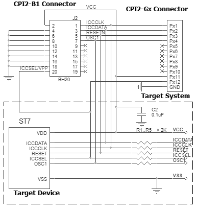
Powering the target device:
There are two alternative options for powering the targets:
1. The target gets power from the programmer (Vdd). This is possible only if the target does not consume too much energy. A capacity of the target power circuitry should not exceed 50 uF.
2. The target gets power from a built-in or external power supply. In this case the power output from the programmer should not be connected with the target. The target system should be tolerant to applying logical signals with the voltage levels exceeding the voltages on the target.
NOTE! It is strictly prohibited to power the target from both the programmer and built-in or external power supply simultaneously.
Isolating resistors:
Purpose of the resistors is to isolate the programmed chip from rest of target system. Recommended value of resistors is 2k or more. You can also use jumpers instead of the resistors.
ISP characteristics:
1. Programmer''s output capability:
1.1 Vcc - 80 mA with powering from USB and 350mA from external device programmer power supply;
1.2 Vpp - 50 mA;
1.3 logical pins - 5 mA.
2. The cable length should be less then one foot.
/Start is the input signal, active state is 0. This signal works as the Start button on the programmer.
/Error, /Good, /Busy are output logical signals, active state is 0. They indicate the programmer status and work as the corresponding LEDs on the programmer case.
Adapter Connection Table:
Connection for the STMicroelectronics STM32 devices in the BootLoader (BL) Mode
Recommended connection:
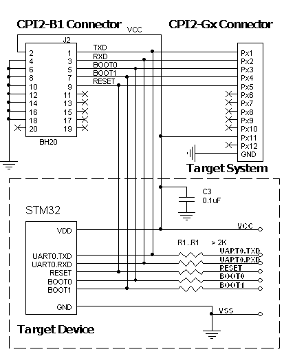
Powering the target device:
There are two alternative options for powering the targets:
1. The target gets power from the programmer (Vdd). This is possible only if the target does not consume too much energy. A capacity of the target power circuitry should not exceed 50 uF.
2. The target gets power from a built-in or external power supply. In this case the power output from the programmer should not be connected with the target. The target system should be tolerant to applying logical signals with the voltage levels exceeding the voltages on the target.
NOTE! It is strictly prohibited to power the target from both the programmer and built-in or external power supply simultaneously.
Isolating resistors:
Purpose of the resistors is to isolate the programmed chip from rest of target system. Recommended value of resistors is 2k or more. You can also use jumpers instead of the resistors.
ISP characteristics:
1. Programmer''s output capability:
1.1 Vcc - 80 mA with powering from USB and 350mA from external device programmer power supply;
1.2 Vpp - 50 mA;
1.3 logical pins - 5 mA.
2. The cable length should be less then one foot.
/Start is the input signal, active state is 0. This signal works as the Start button on the programmer.
/Error, /Good, /Busy are output logical signals, active state is 0. They indicate the programmer status and work as the corresponding LEDs on the programmer case.
Adapter Connection Table:
Connection for the STMicroelectronics STM8 devices
Recommended connection:
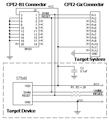
Powering the target device:
There are two alternative options for powering the targets:
1. The target gets power from the programmer (Vdd). This is possible only if the target does not consume too much energy. A capacity of the target power circuitry should not exceed 50 uF.
2. The target gets power from a built-in or external power supply. In this case the power output from the programmer should not be connected with the target. The target system should be tolerant to applying logical signals with the voltage levels exceeding the voltages on the target.
NOTE! It is strictly prohibited to power the target from both the programmer and built-in or external power supply simultaneously.
Isolating resistors:
Purpose of the resistors is to isolate the programmed chip from rest of target system. Recommended value of resistors is 2k or more. You can also use jumpers instead of the resistors.
ISP characteristics:
1. Programmer''s output capability:
1.1 Vcc - 80 mA with powering from USB and 350mA from external device programmer power supply;
1.2 Vpp - 50 mA;
1.3 logical pins - 5 mA.
2. The cable length should be less then one foot.
/Start is the input signal, active state is 0. This signal works as the Start button on the programmer.
/Error, /Good, /Busy are output logical signals, active state is 0. They indicate the programmer status and work as the corresponding LEDs on the programmer case.
Adapter Connection Table:
Connection for the Semtech/XEMICS devices
Recommended connection:
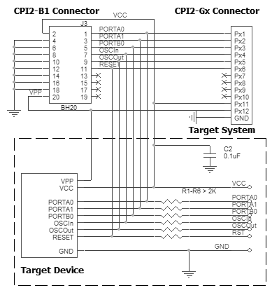
Powering the target device:
There are two alternative options for powering the targets:
1. The target gets power from the programmer (Vdd). This is possible only if the target does not consume too much energy. A capacity of the target power circuitry should not exceed 50 uF.
2. The target gets power from a built-in or external power supply. In this case the power output from the programmer should not be connected with the target. The target system should be tolerant to applying logical signals with the voltage levels exceeding the voltages on the target.
NOTE! It is strictly prohibited to power the target from both the programmer and built-in or external power supply simultaneously.
Isolating resistors:
Purpose of the resistors is to isolate the programmed chip from rest of target system. Recommended value of resistors is 2k or more. You can also use jumpers instead of the resistors.
ISP characteristics:
1. Programmer''s output capability:
1.1 Vcc - 80 mA with powering from USB and 350mA from external device programmer power supply;
1.2 Vpp - 50 mA;
1.3 logical pins - 5 mA.
2. The cable length should be less then one foot.
/Start is the input signal, active state is 0. This signal works as the Start button on the programmer.
/Error, /Good, /Busy are output logical signals, active state is 0. They indicate the programmer status and work as the corresponding LEDs on the programmer case.
Adapter Connection Table:
Connection for the Silicon Labs JTAG microcontrollers
Recommended connection:
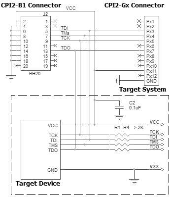
Powering the target device:
There are two alternative options for powering the targets:
1. The target gets power from the programmer (Vdd). This is possible only if the target does not consume too much energy. A capacity of the target power circuitry should not exceed 50 uF.
2. The target gets power from a built-in or external power supply. In this case the power output from the programmer should not be connected with the target. The target system should be tolerant to applying logical signals with the voltage levels exceeding the voltages on the target.
NOTE! It is strictly prohibited to power the target from both the programmer and built-in or external power supply simultaneously.
Isolating resistors:
Purpose of the resistors is to isolate the programmed chip from rest of target system. Recommended value of resistors is 2k or more. You can also use jumpers instead of the resistors.
ISP characteristics:
1. Programmer''s output capability:
1.1 Vcc - 80 mA with powering from USB and 350mA from external device programmer power supply;
1.2 Vpp - 50 mA;
1.3 logical pins - 5 mA.
2. The cable length should be less then one foot.
/Start is the input signal, active state is 0. This signal works as the Start button on the programmer.
/Error, /Good, /Busy are output logical signals, active state is 0. They indicate the programmer status and work as the corresponding LEDs on the programmer case.
Adapter Connection Table:
Connection for the Silicon Labs microcontrollers
Recommended connection:
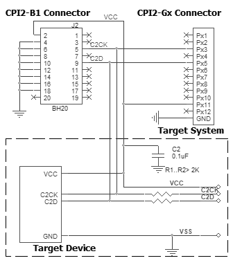
Powering the target device:
There are two alternative options for powering the targets:
1. The target gets power from the programmer (Vdd). This is possible only if the target does not consume too much energy. A capacity of the target power circuitry should not exceed 50 uF.
2. The target gets power from a built-in or external power supply. In this case the power output from the programmer should not be connected with the target. The target system should be tolerant to applying logical signals with the voltage levels exceeding the voltages on the target.
NOTE! It is strictly prohibited to power the target from both the programmer and built-in or external power supply simultaneously.
Isolating resistors:
Purpose of the resistors is to isolate the programmed chip from rest of target system. Recommended value of resistors is 2k or more. You can also use jumpers instead of the resistors.
ISP characteristics:
1. Programmer''s output capability:
1.1 Vcc - 80 mA with powering from USB and 350mA from external device programmer power supply;
1.2 Vpp - 50 mA;
1.3 logical pins - 5 mA.
2. The cable length should be less then one foot.
/Start is the input signal, active state is 0. This signal works as the Start button on the programmer.
/Error, /Good, /Busy are output logical signals, active state is 0. They indicate the programmer status and work as the corresponding LEDs on the programmer case.
Adapter Connection Table:
Connection for the TI CC25xx devices
Recommended connection:
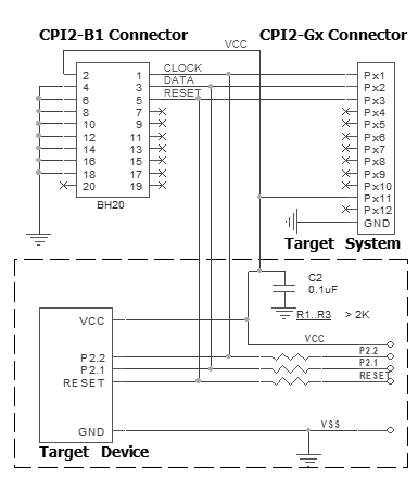
Powering the target device:
There are two alternative options for powering the targets:
1. The target gets power from the programmer (Vdd). This is possible only if the target does not consume too much energy. A capacity of the target power circuitry should not exceed 50 uF.
2. The target gets power from a built-in or external power supply. In this case the power output from the programmer should not be connected with the target. The target system should be tolerant to applying logical signals with the voltage levels exceeding the voltages on the target.
NOTE! It is strictly prohibited to power the target from both the programmer and built-in or external power supply simultaneously.
Isolating resistors:
Purpose of the resistors is to isolate the programmed chip from rest of target system. Recommended value of resistors is 2k or more. You can also use jumpers instead of the resistors.
ISP characteristics:
1. Programmer''s output capability:
1.1 Vcc - 80 mA with powering from USB and 350mA from external device programmer power supply;
1.2 Vpp - 50 mA;
1.3 logical pins - 5 mA.
2. The cable length should be less then one foot.
/Start is the input signal, active state is 0. This signal works as the Start button on the programmer.
/Error, /Good, /Busy are output logical signals, active state is 0. They indicate the programmer status and work as the corresponding LEDs on the programmer case.
Adapter Connection Table:
Connection for the TI MSP430 devices in the BSL Mode with the TEST pin
Recommended connection:
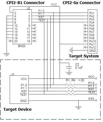
Powering the target device:
There are two alternative options for powering the targets:
1. The target gets power from the programmer (Vdd). This is possible only if the target does not consume too much energy. A capacity of the target power circuitry should not exceed 50 uF.
2. The target gets power from a built-in or external power supply. In this case the power output from the programmer should not be connected with the target. The target system should be tolerant to applying logical signals with the voltage levels exceeding the voltages on the target.
NOTE! It is strictly prohibited to power the target from both the programmer and built-in or external power supply simultaneously.
Isolating resistors:
Purpose of the resistors is to isolate the programmed chip from rest of target system. Recommended value of resistors is 2k or more. You can also use jumpers instead of the resistors.
ISP characteristics:
1. Programmer''s output capability:
1.1 Vcc - 80 mA with powering from USB and 350mA from external device programmer power supply;
1.2 Vpp - 50 mA;
1.3 logical pins - 5 mA.
2. The cable length should be less then one foot.
/Start is the input signal, active state is 0. This signal works as the Start button on the programmer.
/Error, /Good, /Busy are output logical signals, active state is 0. They indicate the programmer status and work as the corresponding LEDs on the programmer case.
Adapter Connection Table:
Connection for the TI MSP430F13x/14x devices in the BSL Mode
Recommended connection:
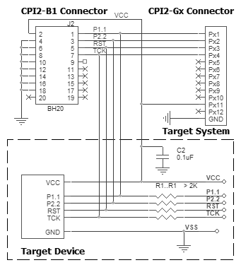
Powering the target device:
There are two alternative options for powering the targets:
1. The target gets power from the programmer (Vdd). This is possible only if the target does not consume too much energy. A capacity of the target power circuitry should not exceed 50 uF.
2. The target gets power from a built-in or external power supply. In this case the power output from the programmer should not be connected with the target. The target system should be tolerant to applying logical signals with the voltage levels exceeding the voltages on the target.
NOTE! It is strictly prohibited to power the target from both the programmer and built-in or external power supply simultaneously.
Isolating resistors:
Purpose of the resistors is to isolate the programmed chip from rest of target system. Recommended value of resistors is 2k or more. You can also use jumpers instead of the resistors.
ISP characteristics:
1. Programmer''s output capability:
1.1 Vcc - 80 mA with powering from USB and 350mA from external device programmer power supply;
1.2 Vpp - 50 mA;
1.3 logical pins - 5 mA.
2. The cable length should be less then one foot.
/Start is the input signal, active state is 0. This signal works as the Start button on the programmer.
/Error, /Good, /Busy are output logical signals, active state is 0. They indicate the programmer status and work as the corresponding LEDs on the programmer case.
Adapter Connection Table:
Connection for the TI MSP430F4xx devices in the BSL Mode
Recommended connection:
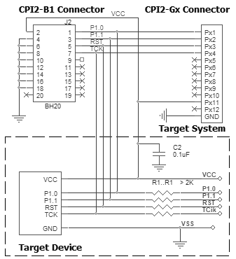
Powering the target device:
There are two alternative options for powering the targets:
1. The target gets power from the programmer (Vdd). This is possible only if the target does not consume too much energy. A capacity of the target power circuitry should not exceed 50 uF.
2. The target gets power from a built-in or external power supply. In this case the power output from the programmer should not be connected with the target. The target system should be tolerant to applying logical signals with the voltage levels exceeding the voltages on the target.
NOTE! It is strictly prohibited to power the target from both the programmer and built-in or external power supply simultaneously.
Isolating resistors:
Purpose of the resistors is to isolate the programmed chip from rest of target system. Recommended value of resistors is 2k or more. You can also use jumpers instead of the resistors.
ISP characteristics:
1. Programmer''s output capability:
1.1 Vcc - 80 mA with powering from USB and 350mA from external device programmer power supply;
1.2 Vpp - 50 mA;
1.3 logical pins - 5 mA.
2. The cable length should be less then one foot.
/Start is the input signal, active state is 0. This signal works as the Start button on the programmer.
/Error, /Good, /Busy are output logical signals, active state is 0. They indicate the programmer status and work as the corresponding LEDs on the programmer case.
Adapter Connection Table:
Connection for the TI MSP430F5xx devices in the BSL Mode
Recommended connection:
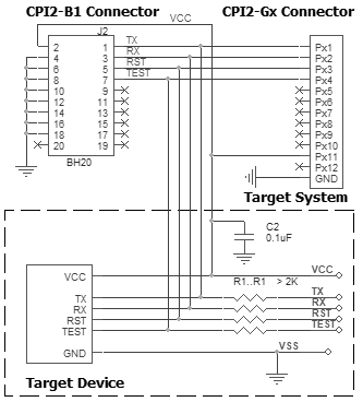
Powering the target device:
There are two alternative options for powering the targets:
1. The target gets power from the programmer (Vdd). This is possible only if the target does not consume too much energy. A capacity of the target power circuitry should not exceed 50 uF.
2. The target gets power from a built-in or external power supply. In this case the power output from the programmer should not be connected with the target. The target system should be tolerant to applying logical signals with the voltage levels exceeding the voltages on the target.
NOTE! It is strictly prohibited to power the target from both the programmer and built-in or external power supply simultaneously.
Isolating resistors:
Purpose of the resistors is to isolate the programmed chip from rest of target system. Recommended value of resistors is 2k or more. You can also use jumpers instead of the resistors.
ISP characteristics:
1. Programmer''s output capability:
1.1 Vcc - 80 mA with powering from USB and 350mA from external device programmer power supply;
1.2 Vpp - 50 mA;
1.3 logical pins - 5 mA.
2. The cable length should be less then one foot.
/Start is the input signal, active state is 0. This signal works as the Start button on the programmer.
/Error, /Good, /Busy are output logical signals, active state is 0. They indicate the programmer status and work as the corresponding LEDs on the programmer case.
Adapter Connection Table:
Connection for the TI MSP430FRxxx devices in JTAG Mode
Recommended connection:
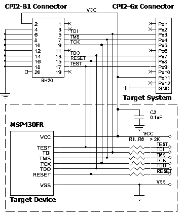
Powering the target device:
There are two alternative options for powering the targets:
1. The target gets power from the programmer (Vdd). This is possible only if the target does not consume too much energy. A capacity of the target power circuitry should not exceed 50 uF.
2. The target gets power from a built-in or external power supply. In this case the power output from the programmer should not be connected with the target. The target system should be tolerant to applying logical signals with the voltage levels exceeding the voltages on the target.
NOTE! It is strictly prohibited to power the target from both the programmer and built-in or external power supply simultaneously.
Isolating resistors:
Purpose of the resistors is to isolate the programmed chip from rest of target system. Recommended value of resistors is 2k or more. You can also use jumpers instead of the resistors.
ISP characteristics:
1. Programmer''s output capability:
1.1 Vcc - 80 mA with powering from USB and 350mA from external device programmer power supply;
1.2 Vpp - 50 mA;
1.3 logical pins - 5 mA.
2. The cable length should be less then one foot.
/Start is the input signal, active state is 0. This signal works as the Start button on the programmer.
/Error, /Good, /Busy are output logical signals, active state is 0. They indicate the programmer status and work as the corresponding LEDs on the programmer case.
Adapter Connection Table:
All power supply pins included AVdd must be powered. All ground pins included AVss must be connected together.
Connection for the TI MSP430FRxxx devices in SBW Mode
Recommended connection:
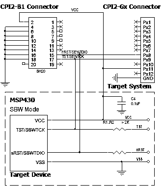
Powering the target device:
There are two alternative options for powering the targets:
1. The target gets power from the programmer (Vdd). This is possible only if the target does not consume too much energy. A capacity of the target power circuitry should not exceed 50 uF.
2. The target gets power from a built-in or external power supply. In this case the power output from the programmer should not be connected with the target. The target system should be tolerant to applying logical signals with the voltage levels exceeding the voltages on the target.
NOTE! It is strictly prohibited to power the target from both the programmer and built-in or external power supply simultaneously.
Isolating resistors:
Purpose of the resistors is to isolate the programmed chip from rest of target system. Recommended value of resistors is 2k or more. You can also use jumpers instead of the resistors.
ISP characteristics:
1. Programmer''s output capability:
1.1 Vcc - 80 mA with powering from USB and 350mA from external device programmer power supply;
1.2 Vpp - 50 mA;
1.3 logical pins - 5 mA.
2. The cable length should be less then one foot.
/Start is the input signal, active state is 0. This signal works as the Start button on the programmer.
/Error, /Good, /Busy are output logical signals, active state is 0. They indicate the programmer status and work as the corresponding LEDs on the programmer case.
Adapter Connection Table:
All power supply pins included AVdd must be powered. All ground pins included AVss must be connected together.
Connection for the TI MSP430Fxxx devices in JTAG Mode with TEST pin
Recommended connection:
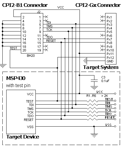
Powering the target device:
There are two alternative options for powering the targets:
1. The target gets power from the programmer (Vdd). This is possible only if the target does not consume too much energy. A capacity of the target power circuitry should not exceed 50 uF.
2. The target gets power from a built-in or external power supply. In this case the power output from the programmer should not be connected with the target. The target system should be tolerant to applying logical signals with the voltage levels exceeding the voltages on the target.
NOTE! It is strictly prohibited to power the target from both the programmer and built-in or external power supply simultaneously.
Isolating resistors:
Purpose of the resistors is to isolate the programmed chip from rest of target system. Recommended value of resistors is 2k or more. You can also use jumpers instead of the resistors.
ISP characteristics:
1. Programmer''s output capability:
1.1 Vcc - 80 mA with powering from USB and 350mA from external device programmer power supply;
1.2 Vpp - 50 mA;
1.3 logical pins - 5 mA.
2. The cable length should be less then one foot.
/Start is the input signal, active state is 0. This signal works as the Start button on the programmer.
/Error, /Good, /Busy are output logical signals, active state is 0. They indicate the programmer status and work as the corresponding LEDs on the programmer case.
Adapter Connection Table:
All power supply pins included AVdd must be powered. All ground pins included AVss must be connected together.
Connection for the TI MSP430Fxxx devices in JTAG Mode without TEST pin
Recommended connection:
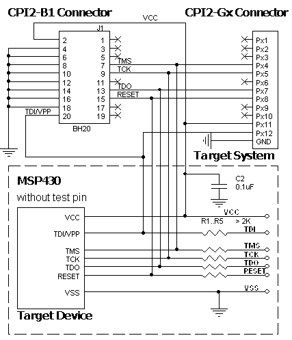
Powering the target device:
There are two alternative options for powering the targets:
1. The target gets power from the programmer (Vdd). This is possible only if the target does not consume too much energy. A capacity of the target power circuitry should not exceed 50 uF.
2. The target gets power from a built-in or external power supply. In this case the power output from the programmer should not be connected with the target. The target system should be tolerant to applying logical signals with the voltage levels exceeding the voltages on the target.
NOTE! It is strictly prohibited to power the target from both the programmer and built-in or external power supply simultaneously.
Isolating resistors:
Purpose of the resistors is to isolate the programmed chip from rest of target system. Recommended value of resistors is 2k or more. You can also use jumpers instead of the resistors.
ISP characteristics:
1. Programmer''s output capability:
1.1 Vcc - 80 mA with powering from USB and 350mA from external device programmer power supply;
1.2 Vpp - 50 mA;
1.3 logical pins - 5 mA.
2. The cable length should be less then one foot.
/Start is the input signal, active state is 0. This signal works as the Start button on the programmer.
/Error, /Good, /Busy are output logical signals, active state is 0. They indicate the programmer status and work as the corresponding LEDs on the programmer case.
Adapter Connection Table:
All power supply pins included AVdd must be powered. All ground pins included AVss must be connected together.
Connection for the TI MSP430Fxxx devices in SBW Mode
Recommended connection:
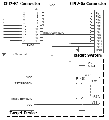
Powering the target device:
There are two alternative options for powering the targets:
1. The target gets power from the programmer (Vdd). This is possible only if the target does not consume too much energy. A capacity of the target power circuitry should not exceed 50 uF.
2. The target gets power from a built-in or external power supply. In this case the power output from the programmer should not be connected with the target. The target system should be tolerant to applying logical signals with the voltage levels exceeding the voltages on the target.
NOTE! It is strictly prohibited to power the target from both the programmer and built-in or external power supply simultaneously.
Isolating resistors:
Purpose of the resistors is to isolate the programmed chip from rest of target system. Recommended value of resistors is 2k or more. You can also use jumpers instead of the resistors.
ISP characteristics:
1. Programmer''s output capability:
1.1 Vcc - 80 mA with powering from USB and 350mA from external device programmer power supply;
1.2 Vpp - 50 mA;
1.3 logical pins - 5 mA.
2. The cable length should be less then one foot.
/Start is the input signal, active state is 0. This signal works as the Start button on the programmer.
/Error, /Good, /Busy are output logical signals, active state is 0. They indicate the programmer status and work as the corresponding LEDs on the programmer case.
Adapter Connection Table:
All power supply pins included AVdd must be powered. All ground pins included AVss must be connected together.
Connection for the YSpring MDT devices
Recommended connection:
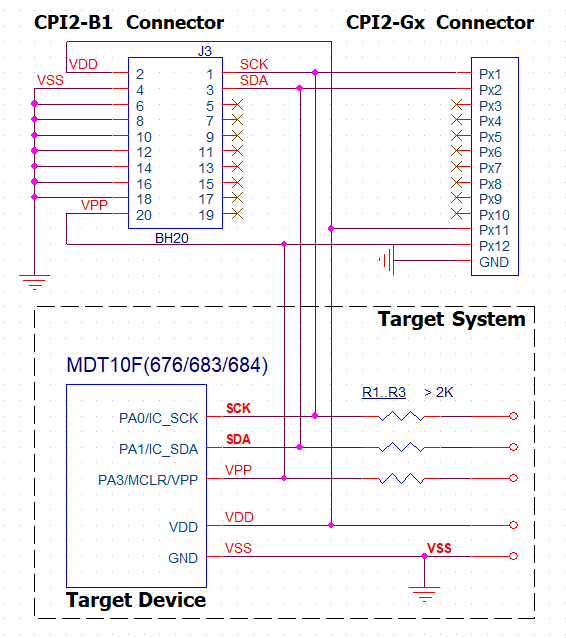
Powering the target device:
There are two alternative options for powering the targets:
1. The target gets power from the programmer (Vdd). This is possible only if the target does not consume too much energy. A capacity of the target power circuitry should not exceed 50 uF.
2. The target gets power from a built-in or external power supply. In this case the power output from the programmer should not be connected with the target. The target system should be tolerant to applying logical signals with the voltage levels exceeding the voltages on the target.
NOTE! It is strictly prohibited to power the target from both the programmer and built-in or external power supply simultaneously.
Isolating resistors:
Purpose of the resistors is to isolate the programmed chip from rest of target system. Recommended value of resistors is 2k or more. You can also use jumpers instead of the resistors.
ISP characteristics:
1. Programmer''s output capability:
1.1 Vcc - 80 mA with powering from USB and 350mA from external device programmer power supply;
1.2 Vpp - 50 mA;
1.3 logical pins - 5 mA.
2. The cable length should be less then one foot.
/Start is the input signal, active state is 0. This signal works as the Start button on the programmer.
/Error, /Good, /Busy are output logical signals, active state is 0. They indicate the programmer status and work as the corresponding LEDs on the programmer case.
Adapter Connection Table:
Connection for the Zilog Z8F devices
Recommended connection:
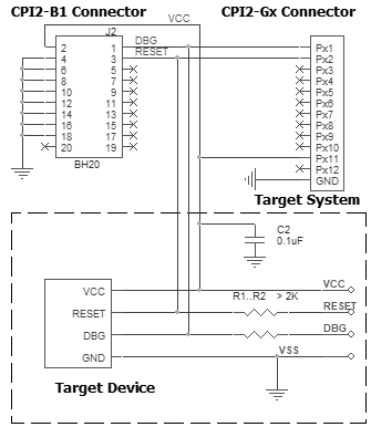
Powering the target device:
There are two alternative options for powering the targets:
1. The target gets power from the programmer (Vdd). This is possible only if the target does not consume too much energy. A capacity of the target power circuitry should not exceed 50 uF.
2. The target gets power from a built-in or external power supply. In this case the power output from the programmer should not be connected with the target. The target system should be tolerant to applying logical signals with the voltage levels exceeding the voltages on the target.
NOTE! It is strictly prohibited to power the target from both the programmer and built-in or external power supply simultaneously.
Isolating resistors:
Purpose of the resistors is to isolate the programmed chip from rest of target system. Recommended value of resistors is 2k or more. You can also use jumpers instead of the resistors.
ISP characteristics:
1. Programmer''s output capability:
1.1 Vcc - 80 mA with powering from USB and 350mA from external device programmer power supply;
1.2 Vpp - 50 mA;
1.3 logical pins - 5 mA.
2. The cable length should be less then one foot.
/Start is the input signal, active state is 0. This signal works as the Start button on the programmer.
/Error, /Good, /Busy are output logical signals, active state is 0. They indicate the programmer status and work as the corresponding LEDs on the programmer case.
Adapter Connection Table:
Adapter connection table: