Device: TesterISP2 [ISP Mode]
- Manufacturer(s): Tests
- Device type: Microcontroller
Tests TesterISP2 [ISP Mode] is programmed "in-system", i.e. being installed on a board. The matrix below lists Phyton device programmers that support the TesterISP2 [ISP Mode] device in-system programming and appropriate cable-Adapters or device library licenses.
| TesterISP2 [ISP Mode] is programmed by | ||
|---|---|---|
| Connection or Adapter | Device programmers | Required license |
| Connection diagrams | CPI2-B1, CPI2-Gx | Covered by free basic license |
| Connection diagrams | CPI2-B1-x (preloaded) | Covered by free basic license |
Recommended CPI2-B1&CPI2-Gx connection (AE-ISP-ST7 connection for the ADAM2xx devices)
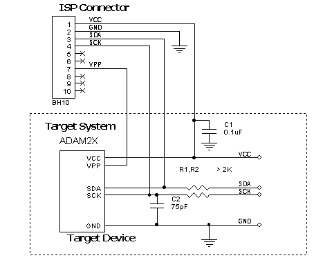
Powering the target device:
The target gets power from the programmer (Vdd). This is possible only if the target does not consume too much energy. A capacity of the target power circuitry should not exceed 50 uF.
NOTE! It is strictly prohibited to power the target from both the programmer and built-in or external power supply simultaneously.
Isolating resistors:
Purpose of the R1,R2 resistors is to isolate the programmed chip from rest of target system. Recommended value of resistors R1,R2 is 2k or more. You can also use jumpers instead of the resistors.
ISP characteristics:
1. Programmer''s output capability:
1.1 Vcc - 80 mA;
1.2 Vpp - 50 mA;
1.3 logical pins - 5 mA.
2. The cable length should be less then one foot.
Adapter Connection Table:
Go Back